


Reference Manual
00809-0100-4021, Rev DA
November 2004
Rosemount 3144P
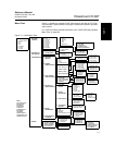
2-16
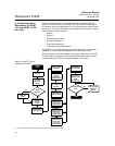
Shielding Recommendations
The following are recommended practices are from API Standard 552
(Transmission Standard) section 20.7 and from field and laboratory testing. If
more than one recommendation is given for a sensor type, start with the first
technique shown or the technique that is recommended for the facility by its
installation drawings. If the technique does not eliminate the transmitter
alarms, try another technique. If all techniques unsuccessfully prevent
transmitter alarms due to high EMI, contact a Emerson Process Management
representative.
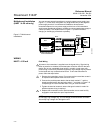
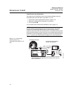
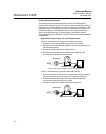
Ungrounded Thermocouple, mV, and RTD/Ohm Inputs
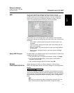
Option 1: recommended for ungrounded transmitter housing
1. Connect the signal wiring shield to the sensor wiring shield.
2. Ensure the two shields are tied together and electrically isolated from
the transmitter housing.
3. Ground the shield at the power supply end only.
4. Ensure the shield at the sensor is electrically isolated from the
surrounding fixtures that may be grounded.
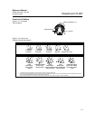
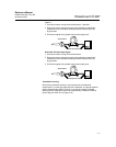
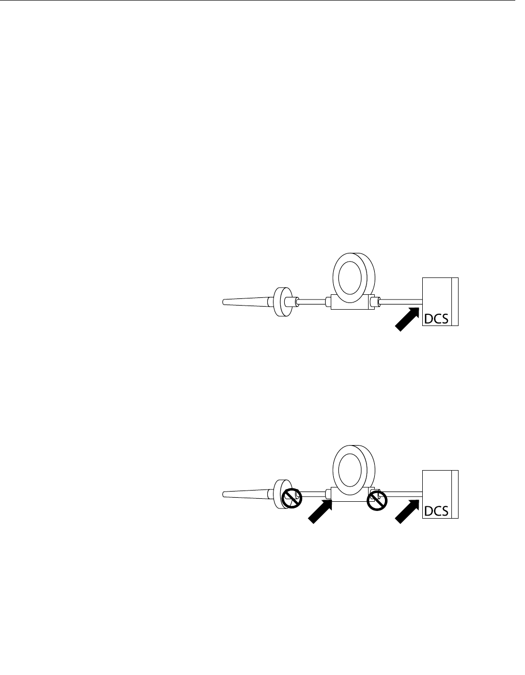
Option 2: recommended for grounded transmitter housing
1. Connect the sensor wiring shield to the transmitter housing, provided
the transmitter housing is grounded (see "Transmitter Housing").
2. Ensure the shield at the sensor end is electrically isolated from
surrounding fixtures that may be grounded.
3. Ground the signal wiring shield at the power supply end.
Sensor Wires
Connect shields together, electrically isolated from the transmitter
Shield ground point
Sensor Wires
Shield ground points