


Reference Manual
00809-0100-4021, Rev DA
November 2004
2-17
Rosemount 3144P
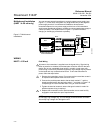
Option 3
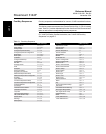
1. Ground the sensor wiring shield at the sensor, if possible.
2. Ensure the sensor wiring and signal wiring shields are electrically
isolated form the transmitter housing and other fixtures that may
be grounded.
3. Ground the signal wiring shield at the power supply end.
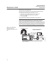
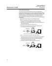
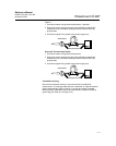
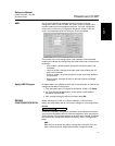
Grounded Thermocouple Inputs
1. Ground the sensor wiring shield at the sensor.
2. Ensure the sensor wiring and signal wiring shields are electrically
isolated form the transmitter housing and other fixtures that may
be grounded.
3. Ground the signal wiring shield at the power supply end.
Transmitter Housing
Ground the transmitter housing in accordance with local electrical
requirements. An internal ground terminal is standard. An optional external
ground lug assembly (Option Code G1) can also be ordered if needed.
Ordering certain hazardous approvals automatically includes an external
ground lug (see Table A-5 on page A-16).
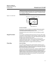
Sensor Wires
Shield ground points
Sensor Wires
Shield ground points