


Reference Manual
00809-0100-4021, Rev DA
November 2004
Rosemount 3144P
3-32
HART
EMF compensation allows the transmitter to provide sensor measurements
that are not affected by unwanted voltages, which are typically due to thermal
EMFs in the equipment connected to the transmitter or by some types of
calibration equipment. If this equipment also requires steady sensor current,
the transmitter must be set to “Active Calibrator Mode.” However, the steady
current does not allow the transmitter to perform EMF compensation. As a
result, a difference in readings between the Active Calibrator and actual
sensor may exist.
If a reading difference is experienced and the difference is greater than the
plant’s accuracy specification allows, perform a sensor trim with “Active
Calibrator Mode” disabled. In this case, an active calibrator capable of
tolerating pulsating sensor current must be used or the actual sensors must
be connected to the transmitter. When the 375 Field Communicator or AMS
asks if an Active Calibrator is being used when the sensor trim routine is
entered, select No. This will leave the “Active Calibrator Mode” disabled.
Contact a Emerson Process Management representative for more
information.
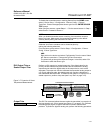
Transmitter-Sensor
Matching
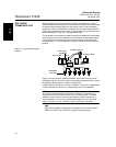
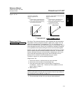
The 3144P accepts Callendar-Van Dusen constants from a calibrated RTD
schedule and generates a special custom curve to match that specific sensor
Resistance vs. Temperature performance. Matching the specific sensor curve
with the transmitter significantly enhances the temperature measurement
accuracy. See the comparison below:
The following input constants, included with specially-ordered Rosemount
temperature sensors, are required:
R
0
= Resistance at Ice Point
Alpha = Sensor Specific Constant
Beta = Sensor Specific Constant
Delta = Sensor Specific Constant
Other sensor may have “A,B, or C” values for constants.
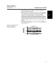
To input Callendar-Van Dusen constants, perform the following procedure:
1. From the HOME screen, select 1 Device Setup, 3 Configuration, 2
Sensor Config, 1 Change Type/Conn., 1 Sensor 1. Select OK after you
set the control loop to manual.
2. Select Cal VanDusen at the ENTER SENSOR TYPE prompt.
3. Select the appropriate number of wires at the ENTER SENSOR
CONNECTION prompt.
4. Enter the R
o
, Alpha, Beta, and Delta values from the stainless steel tag
attached to the special-order sensor when prompted.
5. Select OK after you return the control loop to automatic control.
HART Fast Keys 1, 3, 2, 1, 1
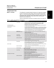
System Accuracy Comparison at 150 °C Using a PT 100 (α=0.00385)
RTD with a Span of 0 to 200 °C
Standard RTD Matched RTD
3144P ±0.10 °C 3144P ±0.10 °C
Standard RTD ±1.05 °C Matched RTD ±0.18 °C
Total System
(1)
(1) Calculated using root-summed-squared (RSS) statistical method
±1.05 °C Total System
(1)
±0.21 °C
TotalSystemAccuracy TransmitterAccuracy()
2
SensorAccuracy()
2
+=