


Reference Manual
00809-0100-4021, Rev DA
November 2004
Rosemount 3144P
2-12
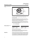
Power/Current Loop Connections
Use copper wire of a sufficient size to ensure that the voltage across the
transmitter power terminals does not go below 12.0 V dc.
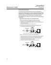
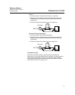
1. Connect the current signal leads as shown in Figure 2-10.
2. Recheck the polarity and correctness of connections.
3. Turn the power ON.
For information about multichannel installations, refer to page 2-17.
NOTE
Do not connect the power/signal wiring to the test terminal. The voltage
present on the power/signal leads may burn out the reverse-polarity
protection diode that is built into the test terminal. If the test terminal’s reverse
polarity protection diode is burned out by the incorrect power/signal wiring, the
transmitter can still be operated by jumping the current from the test terminal
to the “–” terminal. See “Test Terminal” on page 4-3 for use of the terminal.
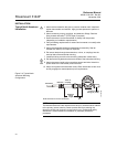
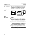
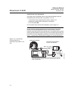
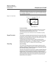
Figure 2-10. m Connecting
a Communicator to a
Transmitter Loop (HART/ 4–20
mA).
Power/Signal Terminals
The signal wire may be grounded at
any point or left ungrounded.
Power
Supply
250 ⍀ ≤ R
L
≤ 1100 ⍀
AMS software or a 375 Field Communicator can be connected at any termination
point in the signal loop. The signal loop must have between 250 and 1100 ohms
load for communications.
3144-0000A04A
or*