


Reference Manual
00809-0100-4021, Rev DA
November 2004
Rosemount 3144P
4-28
FOUNDATION Fieldbus
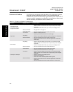
FOUNDATION Fieldbus If a malfunction is suspected despite the absence of a diagnostics message,
follow the procedures described in Table 4-13 to verify that transmitter
hardware and process connections are in good working order. Under each of
symptoms, specific suggestions are offered for solving problems. Always deal
with the most likely and easiest-to-check conditions first.
Table 4-13. F
OUNDATION fieldbus Troubleshooting
Symptom Potential Source Corrective Action
Transmitter does not
Communicate with the
Configuration Interface
Loop Wiring
• Check for adequate voltage to the transmitter. The transmitter requires
between 9.0 and 32.0 V at the terminals to operate and provide complete
functionality
• Check for intermittent wire shorts, open circuits, and multiple grounds.
Network parameters
• See page Table 7-2 on page 7-3
High Output
Sensor Input Failure
or Connection
• Enter the transmitter test mode to isolate a sensor failure.
• Check for a sensor open circuit.
• Check the process variable to see if it is out of range.
Loop Wiring
• Check for dirty or defective terminals, interconnecting pins, or receptacles.
Electronics Module
• Enter the transmitter test mode to isolate a module failure.
• Check the sensor limits to ensure calibration adjustments are within the
sensor range.
Erratic Output
Loop Wiring
• Check for adequate voltage to the transmitter. The transmitter requires
between 9.0 and 32.0 V at the terminals to operate and provide complete
functionality
• Check for intermittent wire shorts, open circuits, and multiple grounds.
Electronics Module
• Enter the transmitter test mode to isolate module failure.
Low Output or No Output
Sensor Element
• Enter the transmitter test mode to isolate a sensor failure.
• Check the process variable to see if it is out of range.
Loop Wiring
• Check for adequate voltage to the transmitter. The transmitter requires
between 9.0 and 32.0 V at the terminals to operate and provide complete
functionality
• Check for wire shorts and multiple grounds.
• Check the loop impedance.
• Check wire insulation to detect possible shorts to ground.
Electronics Module
• Check the sensor limits to ensure calibration adjustments are within the
sensor range.
• Enter the transmitter test mode to isolate an electronics module failure.