


Reference Manual
00809-0100-4021, Rev DA
November 2004
2-15
Rosemount 3144P
NOTE
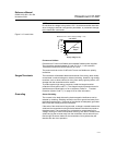
Do not allow the voltage to drop below 12.0 V dc at the transmitter terminals
when changing transmitter configuration parameters, or permanent damage
to the transmitter could result.
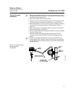
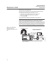
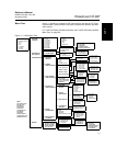
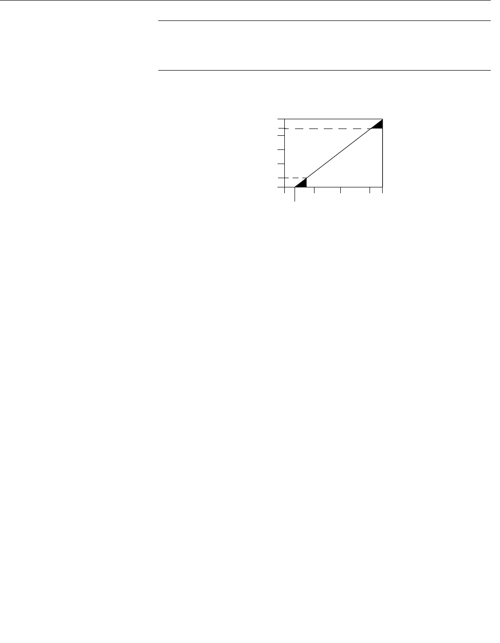
Figure 2-13. Load Limits.
F
OUNDATION fieldbus
Powered over F
OUNDATION fieldbus with standard fieldbus power supplies.
The transmitter operates between 9.0 and 32.0 V dc, 11 mA maximum.
Transmitter power terminals are rated to 42.4 VDC.
The power terminals on the 3144P with F
OUNDATION fieldbus are polarity
insensitive.
Surges/Transients The transmitter will withstand electrical transients of the energy level usually
encountered in static discharges or induced switching. However, high-energy
transients, such as those induced in wiring from nearby lightning strikes, can
damage both the transmitter and the sensor.
To protect against high-energy transients, install the integral transient
protection board (option code T1). The integral transient protection board is
available as an ordered option or as an accessory. Refer to “ Transient
Protection (Option Code T1)” on page A-16 for more information.
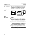
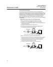
Grounding Sensor Shielding
The currents in the leads induced by electromagnetic interference can be
reduced by shielding. Shielding carries the current to ground and away from
the leads and electronics. If the ends of the shields are adequately grounded,
little current will actually enter the transmitter.
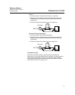
If the ends of the shield are left ungrounded, a voltage is created between the
shield and the transmitter housing and also between the shield and earth at
the element end. The transmitter may not be able to compensate for this
voltage, causing it to lose communication and/or go into alarm. Instead of the
shield carrying the currents away from the transmitter, the currents will now
flow through the sensor leads into the transmitter circuitry where they will
interfere with the circuit operation.
Maximum Load = 40.8 X (Supply Voltage - 12.0)
1240
1000
750
250
0
10
12.0
20 30 40 42.4
Supply Voltage (V dc)
Operating
Region
4–20 mA dc
Load (Ohms)
500
1100