


Reference Manual
00809-0100-4021, Rev DA
November 2004
Rosemount 3144P
A-6
HART / 4–20 MA
SPECIFICATIONS
Power Supply
External power supply required. Transmitters operate on 12.0 to 42.4 V dc
transmitter terminal voltage (with 250 ohm load, 18.1 V dc power supply
voltage is required). Transmitter power terminals rated to 42.4 V dc.
Wiring Diagram
See Figure 1 on page A-13.
Alarms
Custom factory configurations of alarm and saturation levels are available for
valid values with option code C1. These values can also be configured in the
field using a 375 Field Communicator.
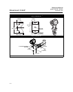
Transient Protection (option code T1)
The transient protector helps to prevent damage to the transmitter from
transients induced on the loop wiring by lightning, welding, heavy electrical
equipment, or switch gears. The transient protection electronics are contained
in an add-on assembly that attaches to the standard transmitter terminal
block. The external ground lug assembly (code G1) is included with the
Transient Protector.The transient protector has been tested per the following
standard:
• IEEE C62.41-1991 (IEEE 587)/ Location Categories B3.
6kV/3kA peak (1.2 ϫ 50 µS Wave 8 ϫ 20 µS Combination Wave)
6kV/0.5kA peak (100 kHz Ring Wave)
EFT, 4kVpeak, 2.5kHz, 5*50nS
• Loop resistance added by protector: 22 ohms max.
• Nominal clamping voltages: 90 V (common mode), 77 V (normal mode)
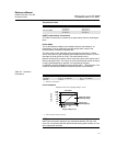
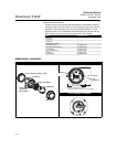
Local Display
Optional five-digit LCD display includes 0–100% bar graph. Digits are
0.4 inches (8 mm) high. Display options include engineering units (°F, °C, °R,
K, ohms, and millivolts), percent, and milliamperes. The display can also be
set to alternate between engineering units/milliamperes, Sensor 1/Sensor 2,
Sensor 1/Sensor 2/Differential Temperature, and Sensor 1/Sensor2/Average
Temperature. All display options, including the decimal point, may be
reconfigured in the field using a 375 Field Communicator or AMS.
Turn-on Time
Performance within specifications is achieved less than 5 seconds (6 seconds
for Safety Certified transmitter) after power is applied to the transmitter when
the damping value is set to 0 seconds.
Power Supply Effect
Less than ±0.005% of span per volt.
SIS Safety Transmitter Failure Values
TÜViT IEC 61508 Safety Certified SIL 2 Claim Limit
• Safety accuracy: 2.0%
(1)
or 2 °C (3.6 °F), whichever is greater
• Safety response time: 5 seconds
(1) A 2% variation of the transmitter mA output is allowed before a safety trip. Trip values in the
DCS or safety logic solver should be derated by 2%.