


Reference Manual
00809-0100-4021, Rev DA
November 2004
4-11
Rosemount 3144P
FOUNDATION Fieldbus
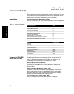
Table 4-7. Sensor Transducer
Block XD_ERR messages
Table 4-8 lists the potential errors and the possible corrective actions for the
given values. The corrective actions are in order of increasing system level
compromises. The first step should always be to reset the transmitter and
then if the error persists, try the steps in Table 4-8. Start with the first
corrective action and then try the second.
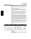
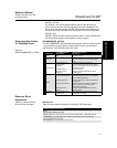
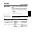
Table 4-8. Sensor Transducer
Block STB.SENSOR_
DETAILED_ STATUS messages
LCD TRANSDUCER
BLOCK
The LCD display connects directly to the 3144P electronics FOUNDATION
fieldbus output board. The meter indicates output and abbreviated diagnostic
messages.
The first line of five characters displays the sensor being measured.
If the measurement is in error, “Error” appears on the first line. The second
line indicates if the device or the sensor is causing the error.
Each parameter configured for display will appear on the LCD for a brief
period before the next parameter is displayed. If the status of the parameter
goes bad, the LCD will also cycle diagnostics following the displayed variable:
Condition Name and Description
Electronics Failure: An electrical component failed.
I/O Failure: An I/O failure occurred.
Software Error: The software has detected an internal error.
Calibration Error: An error occurred during calibration of the device.
Algorithm Error: The algorithm used in the transducer block produced an error due to
overflow, data reasonableness failure, etc.
STB.SENSOR_DETAILED_STATUS Description
Invalid Configuration Wrong sensor connection with wrong sensor
type
ASIC RCV Error The micro detected a chksum or start/stop bit
failure with ASIC communication
ASIC TX Error The ASIC detected a communication error
ASIC Interrupt Error ASIC interrupts are too fast or slow
Reference Error Reference resistors are greater than 25% of
known value
ASIC Configuration Error ASIC registers were not written correctly. (Also
CALIBRATION_ERR)
Sensor Open Open sensor detected
Sensor Shorted Shorted sensor detected
Terminal Temperature Failure Open or shorted PRT detected
Sensor Out of Operating Range Sensor readings have gone beyond
PRIMRY_VALUE_RANGE values
Sensor beyond operating limits Sensor readings have gone below 2% of lower
range or above 6% of upper range of sensor.
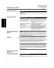
Terminal Temperature Out of Operating
Range
PRT readings have gone beyond
SECONDARY_VALUE_RANGE values
Terminal Temperature Beyond Operating
Limits
PRT readings have gone below 2% of lower
range or above 6% of upper range of PRT.
(These ranges are calculated and are not the
actual range of the PRT which is a PT100 A385)
Sensor Degraded For RTDs, this is excessive EMF detected.
Calibration Error The user trim has failed due to excessive
correction or sensor failure during the trim
method