


Reference Manual
00809-0100-4021, Rev DA
November 2004
B-3
Rosemount 3144P
N1 CENELEC / ATEX Type n Approval (Zone 2)
Certificate Number: BAS01ATEX3432X
ATEX Category Marking II 3 G
EEx nL IIC T6 (T
amb
= –40 to 50 °C)
EEx nL IIC T5 (T
amb
= –40 to 75 °C)
U
i
= 55V
Special Conditions for Safe Use (X):
The transmitter is not capable of withstanding the 500 v insulating test
required by Clause 9.1 of EN50021:1999. This condition must be taken
into account during installation.
I1 CENELEC / ATEX Intrinsic Safety Approval (Zone 0)
Certificate Number: BAS01ATEX1431X
ATEX Category Marking II 1 G
EEx ia IIC T6 (T
amb
= –60 to 50 °C)
EEx ia IIC T5 (T
amb
= –60 to 75 °C)
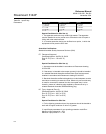
Table B-1. Input Entity
Parameters
Special Conditions for Safe Use (x):
The transmitter is not capable of withstanding the 500V insulation test as
defined in Clause 6.4.12 of EN50 020. This condition must be taken into
account during installation.
Australian Certifications
Standard Australia Quality Assurance Services (SAA)
E7 Flameproof Approval
Certificate Number: AUS Ex 02.3813X
Ex d IIC T6 (T
amb
= –20 to 60 °C)
IP66
Special Conditions for Safe Use (x):
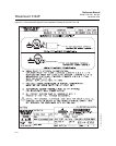
1. Apparatus must be installed in accordance to Rosemount drawing
03144-0325.
2. If the sensor is intended to be remote mounted, it should be installed
in a suitable Standards Australia certified Flame-Proof enclosure and
installed in accordance with Rosemount drawing 03144-0325.
3. Standards Australia certified cable glands or conduit adapters must be
used when connecting to external circuits. Where only one conduit entry
is used for connection to external circuits, the unused entry is to be
closed by means of a blanking plug supplied by Rosemount or by a
suitable Standards Australia certified blanking plug.
Power/Loop Sensor
U
i
= 30 V dc C
i
= 5 nF U
o
= 13.6 V C
i
= 78 nF
I
i
= 300 mA L
i
= 0 I
o
= 56 mA L
i
= 0
P
i
= 1.0 W P
o
=190 mW