


Reference Manual
00809-0100-4021, Rev DA
November 2004
3-9
Rosemount 3144P
HART
Terminal Temperature
The Terminal Temp command sets the terminal temperature units to indicate
the temperature at the transmitter terminals.
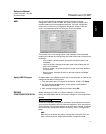
AMS
Right click on the device and select “Configuration Properties” from the
menu. Select the Electronics tab to configure the Terminal Temperature. In
the Terminal Temperature box, Set the Terminal Units to the desired
output.
Apply changes made (see “Apply AMS Changes” on page 3-5).
Dual-Sensor Configuration
Dual-sensor configuration allows configuration of the functions that can be
used with a dual-sensor configured transmitter. This includes Differential
Temperature, Average Temperature, First Good Temperature, Hot Backup,
and Sensor Drift Alert.
Differential Temperature
The 3144P configured for a dual-sensor can accept any two inputs and
display the differential temperature between them. Use the following
procedure to configure the transmitter to measure differential temperature.
First, configure Sensor 1 and Sensor 2 appropriately. Select 1 Device
Setup, 3 Configuration, 2 Sensor Configuration, 1 Change type/conn to set
the sensor type and number of wires for Sensor 1. Repeat for Sensor 2.
NOTE
This procedure reports the differential temperature as the primary variable
analog signal. If this is not necessary, assign differential temperature to the
secondary, tertiary, or quaternary variable.
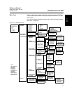
1. From the HOME screen, select 1 Device Setup, 3 Configuration, 1
Variable Mapping, 5 Variable Re-Map to prepare to set the transmitter
to display differential temperature. Set the control loop to manual and
select OK.
2. Select 3Diff from the Primary Variable (PV) menu.
3. Select three of the five variables (average temperature, sensor 1, sensor
2, First-Good, and terminal temperature) for the Secondary Variable
(SV), Tertiary Variable (TV), and Quaternary Variable (QV).
NOTE
The transmitter determines the differential temperature by subtracting
Sensor 2 from Sensor 1 (S1 – S2). Ensure that this order of subtraction is
consistent with the desired reading for the application. Refer to Figure 2-12 on
page 2-16, or inside the transmitter terminal-side cover for sensor wiring
diagrams.
HART Fast Keys 1, 3, 2, 5
HART Fast Keys 1, 3, 3
HART Fast Keys 1, 3, 1, 5, 3