


Reference Manual
00809-0100-4021, Rev DA
November 2004
2-7
Rosemount 3144P
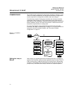
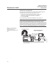
Typical European
Installation
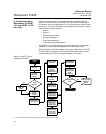
1. Mount the thermowell to the pipe or the process container wall. Install
and tighten thermowells and sensors. Apply pressure and perform a leak
check before starting the process.
2. Attach a connection head to the thermowell.
3. Insert the sensor into the thermowell and wire it to the connection head.
The wiring diagram is located on the inside of the connection head.
4. Mount the transmitter to a 2-inch (50 mm) pipe or a suitable panel using
one of the optional mounting brackets. The B4 bracket is shown in
Figure 2-5.
5. Attach cable glands to the shielded cable running from the connection
head to the transmitter conduit entry.
6. Run the shielded cable from the opposite conduit entry on the transmitter
back to the control room.
7. Insert the shielded cable leads through the cable entries into the
connection head and the transmitter. Connect and tighten the cable
glands.
8. Connect the shielded cable leads to the connection head terminals
(located inside of the connection head) and the sensor wiring terminals
(located inside of the transmitter housing). Avoid contact with the leads
and the terminals.
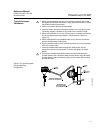
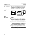
Figure 2-5. Typical European
Process Mounting
Configuration.
644-0000B05B
Cable
Gland
Shielded Cable from
Sensor to Transmitter
Shielded Cable
from Transmitter
to Control Room
2-inch
Pipe
B4
Mounting
Bracket