


Reference Manual
00809-0100-4021, Rev DA
November 2004
Rosemount 3144P
2-14
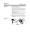
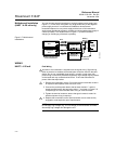
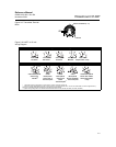
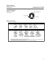
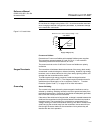
Sensor Connections Figure 2-9 on page 2-11 (HART) and Figure 2-12 on page 2-13 (FOUNDATION
fieldbus) shows the correct sensor wiring connections to the transmitter
sensor terminals. To ensure an adequate sensor connection, anchor the
sensor lead wires beneath the flat washer on the terminal screw. Do not
remove the transmitter cover in explosive atmospheres if the circuit is live.
Both transmitter covers must be fully engaged to meet explosion-proof
requirements. Use extreme caution when making contact with the leads and
terminals.
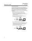
RTD or Ohm Inputs
If the transmitter is mounted remotely from a 3- or 4-wire RTD, it will operate
within specifications, without recalibration, for lead wire resistances of up to
10 ohms per lead (equivalent to 1,000 feet of 20 AWG wire). In this case, the
leads between the RTD and transmitter should be shielded. If using only two
leads (or a compensation loop lead wire configuration), both RTD leads are in
series with the sensor element, so significant errors can occur if the lead
lengths exceed one foot of 20 AWG wire. For longer runs, attach a third or
fourth lead as described above. To eliminate 2-wire lead resistance error, the
2-wire offset command can be used. This allows the user to input the
measured lead wire resistance, resulting in the transmitter adjusting the
temperature to correct the error.
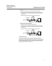
Thermocouple or Millivolt Inputs
For direct-mount applications, connect the thermocouple directly to the
transmitter. If mounting the transmitter remotely from the sensor, use
appropriate thermocouple extension wire. Make connections for millivolt
inputs with copper wire. Use shielding for long runs of wire.
NOTE
For HART transmitters, the use of two grounded thermocouples with a dual
option 3144P transmitter is not recommended. For applications in which the
use of two thermocouples is desired, connect either two ungrounded
thermocouples, one grounded and one ungrounded thermocouple, or one
dual element thermocouple.
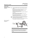
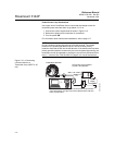
POWER SUPPLY HART
An external power supply is required to operate the 3144P (not included). The
input voltage range of the transmitter is 12 to 42.4 V DC. This is the power
required across the transmitter power terminals. The power terminals are
rated to 42.4 V DC. With 250 ohms of resistance in the loop, the transmitter
will require a minimum of 18.1 V DC for communication.
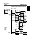
The power supplied to the transmitter is determined by the total loop
resistance and should not drop below the lift-off voltage. The lift-off voltage is
the minimum supply voltage required for any given total loop resistance. See
Figure 2-13 to determine the required supply voltage. If the power drops
below the lift-off voltage while the transmitter is being configured, the
transmitter may output incorrect information.
The dc power supply should provide power with less than 2% ripple. The total
resistance load is the sum of the resistance of the signal leads and the load
resistance of any controller, indicator, or related piece of equipment in the
loop. Note that the resistance of intrinsic safety barriers, if used, must be
included.