


Reference Manual
00809-0100-4021, Rev DA
November 2004
7-3
Rosemount 3144P
Prior Use SIS
Changing Switch
Position
The Failure Mode and Security switches are located on the top center of the
electronics module (see Figure 7-1). The electronics module is on the
electronics side of the transmitter housing. For transmitters with LCD
displays, the electronics module is located behind the LCD display faceplate.
Without a LCD display
1. If the transmitter is installed, set the loop to manual.
2. Remove the housing cover on the electronics side of the transmitter. Do
not remove the transmitter cover in explosive atmospheres when the
circuit is live.
3. Set the switches to the desired position (see Figure 7-1).
4. Replace the transmitter cover. Both transmitter covers must be fully
engaged to meet explosion-proof requirements.
5. Set the loop to automatic control.
With a LCD display
1. If the transmitter is installed, set the loop to manual.
2. Remove the housing cover on the electronics side of the transmitter. Do
not remove the transmitter cover in explosive atmospheres when the
circuit is live.
3. Remove the housing cover, unscrew the LCD display screws and gently
slide the meter straight off.
4. Set the switches to the desired position (see Figure 7-1).
5. Gently slide the LCD display back into place, taking extra precautions of
the 10 pin connection.
6. Secure the LCD display by replacing the LCD display screws.
7. Replace the transmitter cover. Both transmitter covers must be fully
engaged to meet explosion-proof requirements.
8. Set the loop to automatic control.
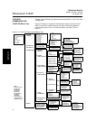
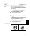
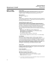
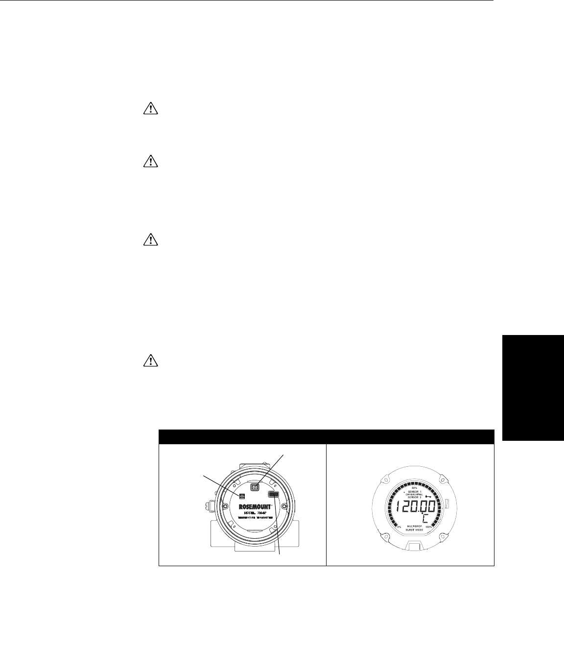
Figure 7-1. Transmitter Jumper
Locations.
Switch Location LCD Display Faceplate
Failure Mode
Security
Diagram of
Switches
Fail Mode and Security Switch
LCD Connector
3144- 0200G33A, 0001B01B