117
Selection and protection of a motor
4
PARAMETERS
4.9 Selection and protection of a motor
4.9.1 Motor protection from overheat (Electronic thermal relay function) (Pr. 9, Pr. 51)
*1 The parameters can be set when Pr. 160 User group read selection = "0" (Refer to page 201)
*2 Performing IPM parameter initialization automatically sets the rated current of the IPM motor. (Refer to page 80)
*3 When parameter is read using the FR-PU04, a parameter name different from an actual parameter is displayed.
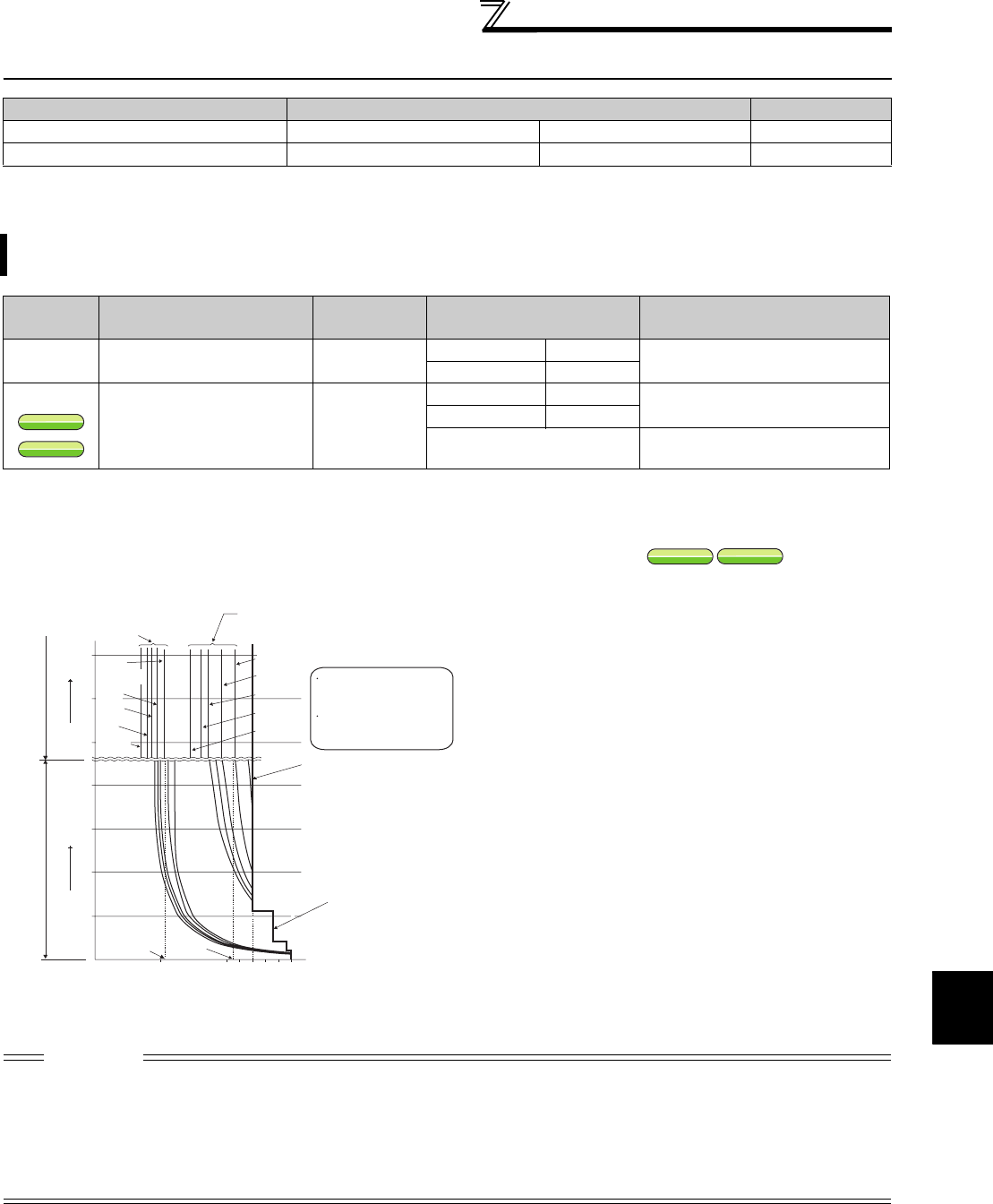
(1) Electronic thermal relay function operation characteristic (THM)
Purpose Parameter that must be Set Refer to page
Motor protection from overheat Electronic thermal O/L relay Pr. 9, Pr. 51 117
Use the constant-torque motor Applied motor Pr. 71 122
Set the current of the electronic thermal O/L relay to protect the motor from overheat. This feature provides the
optimum protective characteristics, including reduced motor cooling capability, at low speed.
Parameter
Number
Name Initial Value Setting Range Description
9
Electronic thermal O/L relay
Rated inverter
current
*2
55K or lower 0 to 500A
Set the rated motor current.
75K or higher 0 to 3600A
51
*1
Second electronic thermal
O/L relay
*3
9999
55K or lower 0 to 500A
Valid when the RT signal is ON.
Set the rated motor current.
75K or higher 0 to 3600A
9999
Second electronic thermal O/L relay
invalid
[Electronic thermal relay function operation characteristic (E.THM)]
This function detects the overload (overheat) of the
motor and the inverter trips. (The operation
characteristic is shown on the left)
⋅ Set the rated current [A] of the motor in Pr. 9.
(If the motor has both 50Hz and 60Hz rating and
the Pr.3 Base frequency is set to 60 Hz, set the 1.1
times of the 60Hz rated motor current.)
⋅ Set "0" in Pr. 9 when you do not want to activate the
electronic thermal relay function, e.g. when using
an external thermal relay with the motor. (Note that
the output transistor protection of the inverter
functions (E.THT).)
⋅ When using the Mitsubishi constant-torque motor
1) Set "1" in Pr. 71. (This provides a 100%
continuous torque characteristic in the low-speed
range.)
2) Set the rated current of the motor in Pr. 9.
*1 When 50% of the inverter rated output current (current value) is
set in Pr. 9
*2 The % value denotes the percentage to the rated inverter
current. It is not the percentage to the rated motor current.
*3 When you set the electronic thermal relay function dedicated to
the Mitsubishi constant-torque motor, this characteristic curve
applies to operation at 6Hz or higher.
CAUTION
⋅ Protective function by electronic thermal relay function is reset by inverter power reset and reset signal input. Avoid
unnecessary reset and power-OFF.
⋅ Install an external thermal relay (OCR) between the inverter and motor for the operation of several motors or of a multi-pole
motor with one inverter. To select a setting for an external thermal relay, consider the line-to-line leakage current in addition to
the current indicated on the motor's rating plate. (For more information on leakage current, refer to page 44.) The cooling effect
of the motor drops during low-speed operation. Use a thermal protector or a motor with built-in thermistor.
⋅ When the difference between the inverter and motor capacities is large and the setting is small, the protective characteristics of
the electronic thermal relay function will be deteriorated. In this case, use an external thermal relay.
V/F
V/F
S
MFVC
S
MFVC
V/F
V/F
S
MFVC
S
MFVC
120
Electronic thermal relay
function for transistor
protection
52.5%
105%
50
100
150
60
120
180
240
50
60
70
6Hz
20Hz
10Hz
6Hz
0.5Hz
30Hz or more*
3
20Hz
10Hz
0.5Hz
Pr. 9 = 50% setting of
inverter rating*
1.2
Pr. 9 = 100% setting
of inverter rating*
1.2
(s) unit display in this range
(min) unit display in
this range
Operation time (min)Operation time (s)
Characteristic when
electronic thermal relay
function for motor
protection is turned OFF
(When Pr. 9 setting is 0(A))
30Hz
or more*
3
Inverter output current(%)
(% to the rated inverter current)
Operation range
Range on the right of
characteristic curve
Non-operation range
Range on the left of
characteristic curve


