


153
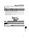
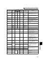
Monitor display and monitor output signal
4
PARAMETERS
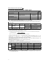
Running speed 1(r/min) 6
*1
6
The value
converted with
the Pr. 37 value
from Pr. 55
Displays the motor speed
(The display
differs depending on the
Pr. 37
and
Pr. 144
settings.)
(For details, refer to page 150 .)
Converter output
voltage
0.1V 8
*1
8
200V class:
400V
400V class:
800V
Displays the DC bus voltage value
Regenerative
brake duty
0.1% 9
*1
9
Pr. 70
Brake duty set in Pr. 30 and Pr. 70 (Setting
is available for the 75K or higher)
Electronic thermal
relay function load
factor
0.1% 10
*1
10 100%
Displays the motor thermal cumulative
value on the assumption that the thermal
operation level is 100%.
Output current
peak value
0.01A/0.1A
*5
11
*1
11
Pr. 56
Retains the peak value of the output
current monitor and displays (clears at
every start)
Converter output
voltage peak
value
0.1V 12
*1
12
200V class:
400V
400V class:
800V
Retains the peak value of the DC bus
voltage value and displays (clears at every
start)
Input power
0.01kW/
0.1kW
*5
13
*1
13
Rated inverter
power
× 2
Displays power of the inverter input side
Output power
0.01kW/
0.1kW
*5
14
*1
14
Rated inverter
power × 2
Displays power of the inverter output side
Load meter
0.1%
17 17 100%
Displays the torque current in % on the
assumption that the Pr. 56 setting is 100%
Cumulative
energization time
*2
1h 20
×
⎯
Displays the cumulative energization time
since the inverter shipment
You can check the numbers of the monitor
value exceeded 65535h with Pr. 563.
Reference voltage
output
⎯⎯
21
⎯
Terminal FM:1440 pulse/s is output
Terminal AM: 10V is output
Actual operation
time
*2*3
1h 23
× ⎯
Displays the cumulative inverter running
time.
You can check the numbers of the monitor
value exceeded 65535h with Pr. 564.
Use Pr. 171 to clear the value.
(Refer to page 156 .)
Motor load factor 0.1% 24 24 200%
Displays the output current value in % on
the assumption that the rated inverter
current value is 100%.
Monitor value = output current monitor
value/rated inverter current
× 100 [%]
Cumulative power
*6
0.01kWh/
0.1kWh
*4,
*5
25
×
⎯
Displays the cumulative power amount
according to the output power monitor
Use Pr. 170 to clear the value.
(Refer to page 156.)
Power saving
effect Variable
according
to
parameters
50 50 Inverter capacity
Displays energy saving effect monitor
You can change the monitor to power
saving, power saving average value,
charge display and % display using
parameters.
(For details, refer to page 178.)
Cumulative saving
power
*6
51
×
⎯
PID set point 0.1% 52 52
100%/
C42 or C44
Displays the set point, measured value and
deviation during PID control
(For details, refer to page 268.)
PID measured
value
0.1% 53 53
100%/
C42 or C44
PID deviation 0.1% 54
× ⎯
Input terminal
status
⎯
55
*1
×
⎯
Displays ON/OFF status of the input
terminal on the PU
(Refer to page 155 for DU display)
Output terminal
status
⎯
*1
×
⎯
Displays ON/OFF status of the output
terminal on the PU
(Refer to page 155 for DU display)
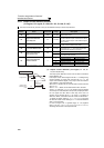
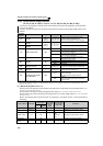
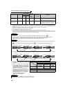
Types of Monitor Increments
Pr. 52 Parameter
Setting Value
Pr. 54 (FM)
Pr. 158 (AM)
Parameter
Setting
Value
Full-scale value
of the terminal
FM and AM
Description
DU LED
PU main
monitor