


141
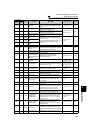
Function assignment of external
terminal and control
4
PARAMETERS
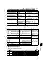
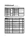
13 113 Y13
Zero current
detection
Output when the output power is lower than
the Pr. 152 setting for longer than the time
set in Pr. 153.
Pr. 152, Pr. 153 146
14 114 FDN PID lower limit
Output when the feedback value falls below
the lower limit of PID control.
Pr. 127 to Pr. 134,
Pr. 575 to Pr. 577
26115 115 FUP PID upper limit
Output when the feedback value rises above
the upper limit of PID control
16 116 RL
PID forward/reverse
rotation output
Output when forward rotation is performed in
PID control.
17 ⎯ MC1
Electronic bypass
MC1
Used when the bypass-inverter switchover
function is used.
These signals are available only under V/F
control and Simple magnetic flux vector
control.
Pr. 135 to Pr. 139,
Pr. 159
27418 ⎯ MC2
Electronic bypass
MC2
19 ⎯ MC3
Electronic bypass
MC3
25 125 FAN Fan fault output Output at the time of a fan alarm. Pr. 244 281
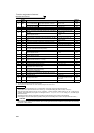
26 126 FIN
Heatsink overheat
pre-alarm
Output when the heatsink temperature
reaches about 85% of the heatsink overheat
protection operation temperature.
⎯ 316
45 145 RUN3
Inverter running and
start command is ON
Output when the inverter is running and start
command is ON.
⎯ 142
46 146 Y46
During deceleration at
occurrence of power
failure (retained until
release)
Output when the power failure-time
deceleration function is executed.
(retained until release)
Pr. 261 to Pr. 266
169
47 147 PID
During PID control
activated
Output during PID control.
Pr. 127 to Pr. 134,
Pr. 575 to Pr. 577
261
48 148 Y48 PID deviation limit
Output when the absolute value of deviation
exceeds the limit value.
Pr. 127 to Pr. 134,
Pr. 241, Pr. 553, Pr.
554, Pr. 575 to Pr.
577, C42 to C45
261
57 157 IPM IPM motor control Output during IPM motor control.
Pr. 71, Pr. 80,
Pr. 998
77
64 164 Y64 During retry Output during retry processing. Pr. 65 to Pr. 69 172
67 167 Y67 During power failure
Output during output shutoff due to power
failure or under voltage.
Pr. 57 168
70 170 SLEEP
PID output
interruption
Output when the PID output interruption
function is executed.
Pr. 127 to Pr. 134,
Pr. 575 to Pr. 577
261
79 179 Y79
Pulse train output of
output power
Output in pulses every time the accumulated
output power of the inverter reaches the
Pr.799 setting.
Pr. 799
149
85 185 Y85 DC current feeding
Output during power failure or under voltage
of AC power.
Pr. 30, Pr. 70 125
90 190 Y90 Life alarm
Output when any of the control circuit
capacitor, main circuit capacitor and inrush
current limit circuit or the cooling fan
approaches the end of its service life.
Pr. 255 to Pr. 259 282
91 191 Y91
Fault output 3
(power-OFF signal)
Output when a fault occurs due to the internal
circuit failure of inverter wiring mistake.
⎯ 143
92 192 Y92
Energy saving
average value
updated timing
Turned ON and OFF alternately every time
the power saving average value is updated
when the power saving monitor is used.
Cannot be set to Pr. 195 and Pr. 196 (relay
output terminal).
Pr. 52, Pr. 54,
Pr. 158, Pr. 891 to
Pr. 899
177
93 193 Y93
Current average
monitor signal
Average current value and maintenance
timer value are output as pulses.
Cannot be set to Pr. 195 and Pr. 196 (relay
output terminal).
Pr. 555 to Pr. 557 286
94 194 ALM2 Fault output 2
Output when the fault occurs. Continues
outputting the signal during inverter reset
and stops outputting after reset is cancelled.
*2
⎯ 143
95 195 Y95
Maintenance timer
signal
Output when Pr. 503 rises to or above the Pr.
504 setting.
Pr. 503, Pr. 504 285
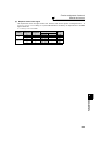
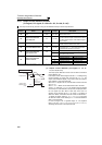
Setting
Signal
Name
Function Operation
Related
Parameters
Refer
to Page
Positive
Logic
Negative
Logic