


266
Special operation and frequency control
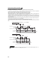
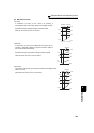
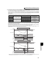
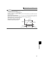
(5) PID control automatic switchover control (Pr. 127)
⋅ The inverter can be started up without PID control mode only at a start.
⋅ When the frequency is set to Pr. 127 PID control automatic switchover frequency within the range of 0 to 400Hz, the
system starts up without PID operation from a start until output frequency reaches Pr. 127, and then it shifts to PID
control operation mode. Once the system has entered PID control operation, it continues PID control if the output
frequency falls to or below Pr. 127.
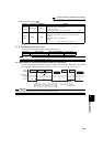
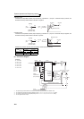
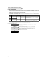
(6) Selecting operation to be performed at the output of Upper limit signal, Lower limit signal,
and PID deviation limit signal (FUP signal, FDN signal, Y48 signal, Pr.554)
You can select the operation to be performed at the detection of upper, lower and deviation limit for the measured
value input. With Pr. 554 PID signal operation selection, signal output or signal output + alarm stop (E.PID) can be
selected for each of upper limit output signal (FUP signal), lower limit output signal (FDN signal), and PID
deviation limit signal (Y48 signal).
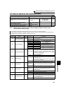
*1 The shaded area indicates the parameter initial value.
*2 For the setting method via L
ONWORKS communication, refer to the LONWORKS communication option (FR-A7NL) instruction manual.
For the setting method via CC-Link communication, refer to the CC-Link communication option (FR-A7NC) instruction manual.
*3 When 100 or larger value is set to any of Pr. 190 to Pr. 196 (output terminal function selection), the terminal output has negative logic. (Refer to
page 140 for details)
*4 When the voltage/current input specifications were changed using Pr. 73 and Pr. 267, be sure to make calibration. (Refer to page 268 for
calibration examples for PID control.)
CAUTION
⋅ Changing the terminal assignment using any of Pr. 178 to Pr. 189, and 190 to Pr. 196 may affect the other functions. Set
parameters after confirming the function of each terminal.
⋅ After changing Pr.73 or Pr.267, check the voltage/current input selection switch. Incorrect setting may cause a fault, failure or
malfunction. (Refer to page 185 for setting.)
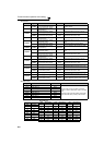
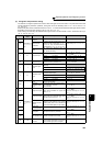
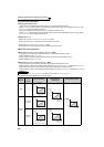
Pr. 554 Setting FUP Signal, FDN Signal * Y48 Signal * SLEEP Function
0 (Initial value) Only signal output
Only signal output
Motor coasts to a stop at the
start of SLEEP operation
1 Signal output + stop by fault (E.PID)
2 Only signal output
Signal output + stop by fault
(E.PID)
3 Signal output + stop by fault (E.PID)
10 Only signal output
Only signal output
Motor decelerates to a stop at
the start of SLEEP operation
11 Signal output + stop by fault (E.PID)
12 Only signal output
Signal output + stop by fault
(E.PID)
13 Signal output + stop by fault (E.PID)
* When the settings for Pr.131 PID upper limit, Pr.132 PID lower limit, and Pr.553 PID deviation limit, which corresponds with FUP, FDN, and Y48 signals, are
"9999" (no function), the signal is not output, or the alarm stop is not performed.
Output frequency
P
r.127
STF
Time
PID
PID control
Without
PID control