


159
Monitor display and monitor output signal
4
PARAMETERS
4.12.4 Terminal FM, AM calibration
(Calibration parameter C0 (Pr. 900), C1 (Pr. 901))
(1) FM terminal calibration (C0(Pr.900))
⋅ The terminal FM is preset to output pulses. By setting the Calibration parameter C0 (Pr. 900), the meter connected to
the inverter can be calibrated by parameter setting without use of a calibration resistor.
⋅ Using the pulse train output of the terminal FM, a digital display can be provided by a digital counter. The monitor
value is 1440 pulses/s output at the full-scale value of the table on the previous page (Pr. 54 FM terminal function
selection).
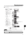
⋅ Calibrate the terminal FM in the following procedure.
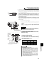
1) Connect an indicator (frequency meter) across the terminals FM and SD of the inverter. (Note the polarity. The
terminal FM is positive.)
2) When a calibration resistor has already been connected, adjust the resistance to "0" or remove the resistor.
3) Refer to the monitor description list (page 152) and set Pr. 54. When you selected the running frequency or
inverter output current as the monitor, preset the running frequency or current value, at which the output signal
will be 1440 pulses/s, to Pr. 55 Frequency monitoring reference or Pr. 56 Current monitoring reference. At 1440 pulses/
s, the meter generally deflects to full-scale.
By using the operation panel or parameter unit, you can calibrate terminal FM and terminal AM to full scale
deflection.
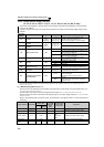
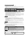
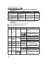
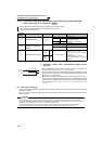
Parameter
Number
Name Initial Value Setting Range Description
C0(900)
*1*2*3
FM terminal calibration ⎯⎯
Calibrates the scale of the meter
connected to terminal FM.
C1(901)
*1*2*3
AM terminal calibration ⎯⎯
Calibrates the scale of the analog
meter connected to terminal AM.
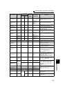
*1 This parameter can be set when Pr. 160 User group read selection = "0". (Refer to page 201.)
*2 This parameter number in parentheses is the one for use with the parameter unit (FR-PU04/FR-PU07).
*3 This parameter allows its setting to be changed during operation in any operation mode even if "0" (initial value) is set in Pr. 77 Parameter write
selection.
*1 Not needed when the operation panel (FR-DU07) or parameter unit (FR-PU04/FR-PU07) is used for calibration. Use a calibration
resistor when the indicator (frequency meter) needs to be calibrated by a neighboring device because the indicator is located far from
the inverter. However, the frequency meter needle may not deflect to full-scale if the calibration resistor is connected. In this case,
perform calibration using the operation panel or parameter unit.
REMARKS
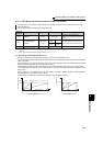
⋅ When calibrating a monitor output signal, which cannot be adjusted to 100% value without an actual load and a measurement
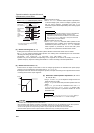
equipment, set Pr. 54 to "21" (reference voltage output). 1440 pulses/s are output from the terminal FM.
1440 pulses/s are output
from the terminal FM.
⋅ The wiring length of the terminal FM should be 200m maximum.
CAUTION
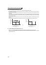
⋅ The initial value of the calibration parameter C0 (Pr.900) is set to 1mA full scale and 1440 pulse/s FM output frequency when
the inverter output frequency is 60Hz. The maximum pulse train output of terminal FM is 2400 pulses/s.
⋅ When a frequency meter is connected to across terminals FM-SD to monitor the running frequency, the FM terminal output
is filled to capacity at the initial setting if the maximum output frequency reaches or exceeds 100Hz. In this case, the
Pr. 55
setting must be changed to the maximum frequency.
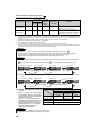
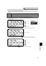
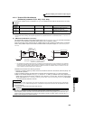
8VDC
T2
T1
Pulse width T1: Adjust using calibration parameter C0
Pulse cycle T2: Set with Pr. 55 (frequency monitor)
Set with Pr.56 (current monitor)
(Digital indicator)
(-)
1440 pulses/s(+)
FM
SD
Indicator
1mA full-scale
analog meter
(+)
1mA
FM
SD
Calibration
resistor
*1
(-)