


195
Frequency setting by analog input (terminal 1, 2, 4)
4
PARAMETERS
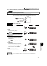
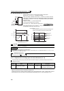
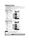
4.17.6 Frequency setting signal (current) bias/gain adjustment method
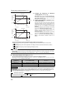
(a)Method to adjust any point by application of voltage (current) across the terminals 2 and 5 (4 and 5).
Perform the following procedure to adjust the bias and gain of the frequency setting voltage (current) using the
operation panel FR-DU07.
Refer to page 193 for the details of parameters.
REMARKS
⋅ If the frequency meter (indicator) connected to across terminals FM and SD does not indicate exactly 60Hz, set calibration
parameter C0 FM terminal calibration. (Refer to page 159)
⋅ If the gain and bias of frequency setting voltage (current) are too close, an error ( ) may be displayed at setting.
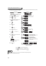
5.
Turn to change it to the setting value
of " ".
4.
Press to read the present set value.
" " (initial value) appears.
3.
Turn until appears.
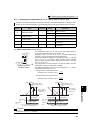
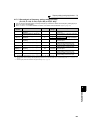
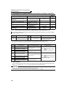
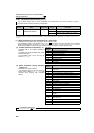
Display
Analog voltage (current)
value (%) across terminals 2 and 5
(across terminals 4 and 5)
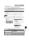
Flicker...Parameter setting complete!!
Flicker...Parameter setting complete!!
*
*
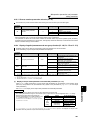
*The value is nearly 100 (%) in the maximum
position of the potentiometer.
*The value is nearly 100 (%) in the maximum
position of the potentiometer.
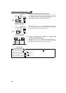
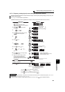
CAUTION
After performing the operation in step 10, do not touch until
completion of calibration.
(Adjustment completed)
Press twice to show the next parameter ( ).
C0 to C7 setting
is enabled.
Terminal 2 input Terminal 4 input
By turning , you can read another parameter.
Press to return to the indication (step 8).
The parameter
number read
previously appears.
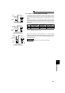
1.
Confirm the RUN indicator and operation
mode indicator
The inverter must be at a stop.
The inverter must be in the PU operation
mode. (Using )
2.
Press to choose the parameter
setting mode.
6.
Press to set.
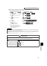
7.
8.
Press to display .
9.
Turn until ( ) appears.
Set to C4 Terminal 2 frequency setting
gain.
10.
Press to display the analog voltage
(current) value (%).
11.
Apply a 5V (20mA) voltage (current).
(Turn the external potentiometer
connected across terminals 2 and 5
(across terminals 4 and 5) to maximum
(any position).)
12.
Press to set.
Operation
Terminal 4 input
Terminal 2 input