373
244
Cooling fan operation
selection
34 B4 2
245
Rated slip
35 B5 2
×
246
Slip compensation time
constant
36 B6 2
×
247
Constant-power range slip
compensation selection
37 B7 2
×
250 Stop selection
3A BA 2
251
Output phase loss protection
selection
3B BB 2
252 Override bias
3C BC 2
253
Override gain
3D BD 2
255
Life alarm status display
3F BF 2
× × ×
256
Inrush current limit circuit life
display
40 C0 2
×××
257
Control circuit capacitor life
display
41 C1 2
× × ×
258
Main circuit capacitor life
display
42 C2 2
×××
259
Main circuit capacitor life
measuring
43 C3 2
260
PWM frequency automatic
switchover
44 C4 2
261
Power failure stop selection
45 C5 2
262
Subtracted frequency at
deceleration start
46 C6 2
263
Subtraction starting frequency
47 C7 2
264
Power-failure deceleration
time 1
48 C8 2
265
Power-failure deceleration
time 2
49 C9 2
266
Power failure deceleration
time switchover frequency
4A CA 2
267
Terminal 4 input selection
4B CB 2
×
268
Monitor decimal digits
selection
4C CC 2
269
Parameter for manufacturer setting. Do not set.
296
Password lock level
68 E8 2
×
297
Password lock/unlock
69 E9 2
*5
299
Rotation direction detection
selection at restarting
6B EB 2
×
300
BCD input bias
00 80 3
301
BCD input gain
01 81 3
302
BIN input bias
02 82 3
303
BIN input gain
03 83 3
304
Digital input and analog input
compensation enable/disable
selection
04 84 3
305
Read timing operation
selection
05 85 3
306
Analog output signal
selection
06 86 3
307
Setting for zero analog
output
07 87 3
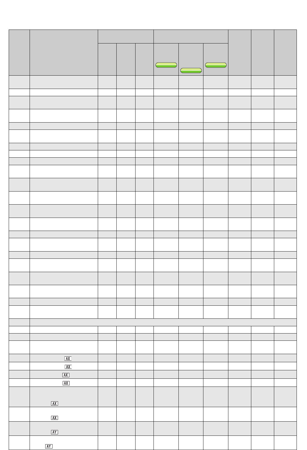
Parameter
Name
Instruction Code *1
Control Mode-based
Correspondence Table
*2
Parameter
Copy
*3
Parameter
Clear
*3
All
Parameter
Clear
*3
Read Write
Extended
V/F
control
Simple
magnetic
flux vector
control
IPM motor
control
V/F
V/F
V/F
S
MFVC
S
MFVC
S
MFVC
IPM
IPM
IPM


