


36
Connection of stand-alone option units
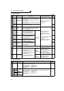
2.4.2 Connection of the brake unit (FR-BU/MT-BU5)
When connecting the brake unit (FR-BU(H)/MT-BU5) to improve the brake capability at deceleration, make connection
as shown below.
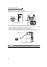
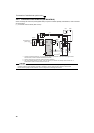
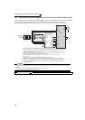
(1) Connection with the FR-BU (55K or lower)
*1 Connect the inverter terminals (P/+, N/-) and brake unit (FR-BU (H)) terminals so that their terminal signals match
with each other. (Incorrect connection will damage the inverter.)
*2 When the power supply is 400V class, install a step-down transformer.
*3 The wiring distance between the inverter, brake unit (FR-BU) and resistor unit (FR-BR) should be within 5m. If
twisted wires are used, the distance should be within 10m.
CAUTION
⋅ If the transistors in the brake unit should become faulty, the resistor can be unusually hot, causing a fire. Therefore, install a
magnetic contactor on the inverter’s input side to configure a circuit so that a current is shut off in case of fault.
⋅ Do not remove a jumper across terminal P/+ and P1 except when connecting a DC reactor.
U
V
W
P/+
N/−
R/L1
S/L2
T/L3
Motor
M
Inverter
PR
N/−
P/+
P
HA
HB
HC
FR-BU
FR-BR
TH2
TH1
PR
*1
Three-phase AC
power supply
MCCB
MC
OFFON
MC
T *2
MC
*3
10m or less