


125
Motor brake and stop operation
4
PARAMETERS
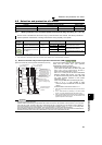
4.10.3 Selection of a regenerative brake and DC feeding (Pr. 30, Pr. 70)
The above parameters can be set when Pr. 160 User group read selection = "0". (Refer to page 201)
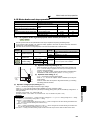
*1 Pr.30 can be set to "1, 11, or 21" for 75K or higher.
*2 Used in combination with GZG, GRZG, or FR-BR.
*3 Used in combination with MT-BR5.
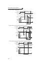
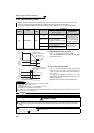
<55K or lower>
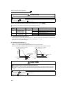
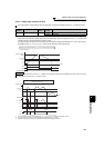
<75K or higher>
*1 Used in combination with GZG, GRZG, or FR-BR.
*2 Used in combination with MT-BR5.
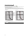
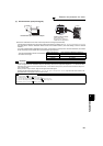
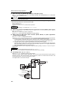
When making frequent starts/stops, use the optional brake unit (FR-BU2, BU, FR-BU, MT-BU5) to increase the
regenerative brake duty.
Use a power regeneration common converter (FR-CV) or power regeneration converter (MT-RC) for
continuous operation in regenerative status.
Use a high power factor converter (FR-HC, MT-HC) to reduce harmonics, improve the power factor, or
continuously use the regenerative mode.
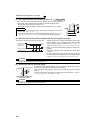
You can select DC feeding mode 1, which operates with DC power supply (terminal P/+, N/-), or DC feeding
mode 2, which normally operates with AC power supply (terminal R/L1, S/L2, T/L3) and with DC power supply
such as battery at power failure occurrence.
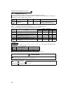
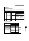
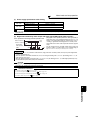
Parameter
Number
Name
Initial
Value
Setting Range Description
30
Regenerative function
selection
0
Regeneration unit
Terminal for power
supply to the inverter
0
Inverter without regenerative
function, brake unit (FR-BU2
*2
, FR-BU, BU type)
R/L1, S/L2, T/L3
10
P/+, N/-
(DC feeding mode 1)
20
R/L1, S/L2, T/L3 - P/+, N/-
(DC feeding mode 2)
1
*1
Brake unit (FR-BU2 *3, MT-
BU5), power regeneration
converter (MT-RC)
R/L1, S/L2, T/L3
11
*1
P/+, N/-
(DC feeding mode 1)
21
*1
R/L1, S/L2, T/L3 - P/+, N/-
(DC feeding mode 2)
2
High power factor converter
(FR-HC, MT-HC), power
regeneration common
converter (FR-CV)
P/+, N/-
70
Special regenerative
brake duty
0% 0 to 10%
Set the %ED of the brake transistor operation when using
a brake unit (MT-BU5).
(Setting is available only for the 75K or higher)
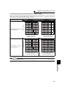
Regeneration Unit Power Supply to the Inverter Pr. 30 Setting
Inverter without regenerative function
,
brake unit (FR-BU2
*1, FR-BU, BU)
R/L1, S/L2, T/L3
0
(initial value)
P/+, N/- 10
R/L1, S/L2, T/L3 - P/+, N/- 20
High power factor converter (FR-HC),
power regeneration common converter
(FR-CV)
P/+, N/- 2
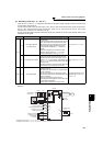
Regeneration Unit Power Supply to the Inverter Pr. 30 Setting Pr. 70 Setting
Inverter without regenerative function
R/L1, S/L2, T/L3
0
(initial value)
⎯
P/+, N/- 10
R/L1, S/L2, T/L3 - P/+, N/- 20
Brake unit (FR-BU2
*2)
R, S, T 1
0%
(initial value)
P, N 11
R, S, T/P, N 21
Power regeneration converter (MT-RC) R/L1, S/L2, T/L3 1
0%
(initial value)
Brake unit (MT-BU5)
R/L1, S/L2, T/L3 1
10%P/+, N/- 11
R/L1, S/L2, T/L3 - P/+, N/- 21
High power factor converter (MT-HC) P/+, N/- 2 ⎯