317
Causes and corrective actions
5
PROTECTIVE FUNCTIONS
Operation Panel
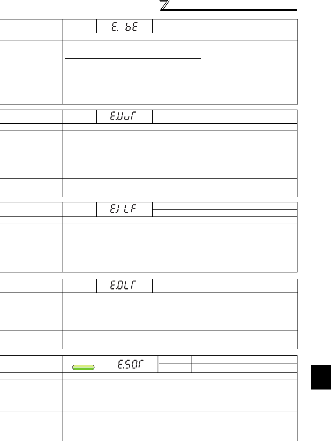
Indication
E.BE
FR-PU04
FR-PU07
Br. Cct. Fault
Name
Brake transistor alarm detection/internal circuit fault
Description
This function stops the inverter output if a fault occurs in the brake circuit, e.g. damaged brake
transistors when using functions of the 75K or higher.
In this case, the inverter must be powered OFF immediately.
For the 55K or lower, it appears when an internal circuit error occurred.
Check point
· Reduce the load inertia.
· Check that the frequency of using the brake is proper.
· Check that the brake resistor selected is correct.
Corrective action
For the 75K or higher, when the protective function is activated even if the above measures are taken,
replace the brake unit with a new one.
For the 55K or lower, replace the inverter.
Operation Panel
Indication
E.UVT
FR-PU04
FR-PU07
Under Voltage
Name
Undervoltage
Description
If the power supply voltage of the inverter decreases, the control circuit will not perform normal functions.
In addition, the motor torque will be insufficient and/or heat generation will increase. To prevent this, if
the power supply voltage decreases below about 150V (300VAC for the 400V class), this function
stops the inverter output.
When a jumper is not connected across P/+ and P1, the undervoltage protective function is activated.
When undervoltage protection is activated, the IPF signal is output. (Refer to page 162)
Check point
· Check for start of large-capacity motor.
· Check that a jumper or DC reactor is connected across terminals P/+ and P1.
Corrective action
· Check the power supply system equipment such as the power supply.
· Connect a jumper or DC reactor across terminals P/+ and P1.
· If the problem still persists after taking the above measure, please contact your sales representative.
Operation Panel
Indication
E.ILF
FR-PU04 Fault 14
FR-PU07 Input phase loss
Name
Input phase loss
Description
This fault is output when function valid setting (=1) is set in Pr. 872 Input phase loss protection selection
and one phase of the three phase power input is lost.
When the setting of Pr. 872 Input phase loss protection selection is the initial value (Pr. 872 = "0"), this fault
does not occur. (Refer to page 175.)
Check point
Check for a break in the cable for the three-phase power supply input.
Corrective action
· Wire the cables properly.
· Repair a break portion in the cable.
· Check the Pr. 872 Input phase loss protection selection setting.
Operation Panel
Indication
E.OLT
FR-PU04
FR-PU07
Stll Prev STP
Name
Stall prevention stop
Description
If the frequency has fallen to 0.5Hz(1.5Hz under IPM motor control) by stall prevention operation and
remains for 3s, a fault (E.OLT) appears and trips the inverter. OL appears while stall prevention is being
activated.
Check point
· Check the motor for use under overload. (Refer to page 92.)
· Check that a motor is connected during IPM motor control. (IPM motor control)
Corrective action
· Reduce the load weight.
· Check the connection of the IPM motor. (IPM motor control)
· Set the IPM motor test operation. (Refer to page 92)
Operation Panel
Indication
E.SOT
FR-PU04
Fault 14
FR-PU07
Motor step out
Name
Loss of synchronism detection
Description
Stops the output when the operation is not synchronized. (This function is only available under IPM
motor control.)
Check point
· Check that the IPM motor is not driven overloaded.
· Check if a start command is given to the inverter while the IPM motor is coasting.
· Check if a motor other than the IPM motor (MM-EFS series or MM-EF series) is driven.
Corrective action
· Set the acceleration time longer.
· Reduce the load.
· If the inverter restarts during coasting, set Pr.57 Restart coasting time ≠ "9999," and select the
automatic restart after instantaneous power failure.
· Drive the IPM motor (MM-EFS series or MM-EF series).
IPM
IPM


