


126
Motor brake and stop operation
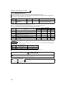
(1) When the brake unit (FR-BU2, BU, FR-BU) is used (55K or lower)
⋅ Set Pr. 30 = "0 (initial setting), 10, or 20" for the FR-BU2 operation with GZG/GRZG/FR-BR, or the BU/FR-BU
operation. The Pr. 70 setting is invalid.
(2) When the FR-BU2 brake unit is used (in combination with MT-BR5) (75K or higher)
Set the following parameters to use FR-BU2 with MT-BR5.
⋅ Set "1, 11, or 21" in Pr. 30.
⋅ Set "0% (initial setting)" in Pr. 70.
⋅ Set "2" in Pr. 0 Brake mode selection, a FR-BU2 brake unit parameter.
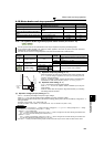
(3) When using a brake unit (MT-BU5) and power regeneration converter (MT-RC) (75K or higher)
⋅ Set "1, 11 or 21" in Pr. 30.
⋅ Set "10%" In Pr. 70 when using a brake unit (MT-BU5).
⋅ Set "0%" in Pr. 70 when using a power regeneration converter (MT-RC).
(4) When using the high power factor converter (FR-HC, MT-HC) or power regeneration
common converter (FR-CV)
⋅ Set "2" in Pr. 30. The Pr. 70 setting becomes invalid.
⋅
Use any of
Pr. 178 to Pr. 189 (Input terminal function assignment)
to assign the following signals to the contact input terminals.
(a) X10 signal: FR-HC, MT-HC connection, FR-CV connection (inverter operation enable signal)
To make protective coordination with the FR-HC, MT-HC or FR-CV, use the inverter operation enable signal
to shut off the inverter output. Input the RDY signal of the FR-HC, MT-HC (RDYB signal of the FR-CV).
(b) X11 signal: FR-HC, MT-HC connection (instantaneous power failure detection signal)
When the setting has been made to hold the mode at occurrence of an instantaneous power failure for RS-
485 communication operation, use this signal to hold the mode. Input the Y1 or Y2 signal (instantaneous
power failure detection signal) of the FR-HC, MT-HC.
⋅ For the terminal used for X10 or X11 signal input, assign its function by setting "10" (X10) or "11" (X11) in any of Pr.
178 to Pr. 189.
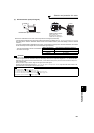
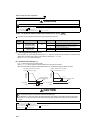
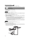
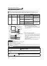
(5) DC feeding mode 1 (Pr. 30 = "10, 11")
⋅ Setting "10, 11" in Pr. 30 enables DC power supply operation.
⋅ Leave the AC power supply connection terminal R/L1, S/L2, and T/L3 open and connect the DC power supply to
terminal P/+ and N/-. Also, remove jumpers across terminal R/L1 and R1/L11 as well as S/L2 and S1/L21, and
connect terminals R1/L11 and S1/L21 to terminal P/+ and N/-.
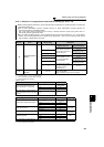
⋅ The diagram below is a connection example.
CAUTION
⋅ Do not operate the MT-BU5 type brake unit and FR-BU2 in parallel. Doing so could cause an alarm or brake unit failure. Use the
FR-BU2 only when performing parallel operation.
REMARKS
⋅ Stall prevention (overvoltage), oL, is disabled when Pr. 30 = "1, 11, or 21."
REMARKS
⋅ The MRS signal can also be used instead of the X10 signal. (Refer to page 135.)
⋅ When Pr. 30 = "2", "Err" is displayed on the operation panel as the inverter is reset by the setting.
R/L1
S/L2
T/L3
U
V
W
P/+
N/-
M
STF
STR
R1/L11
S1/L21
10
2
2
3
1
5
(+)
(-)
MC
Inrush
current
limit circuit
DC power
Forward rotation start
Reverse rotation start
Contact input common
Frequency command
Frequency setting
potentiometer
1/2W1kΩ
Earth
(Ground)
Inverter
SD