


313
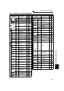
Causes and corrective actions
5
PROTECTIVE FUNCTIONS
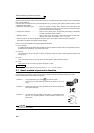
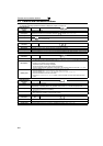
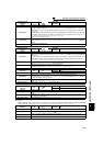
(3) Alarm
When an alarm occurs, the output is not shut off. You can also output an alarm signal by making parameter
setting. (Set "98" in any of Pr. 190 to Pr. 196 (output terminal function selection). (Refer to page
140.)
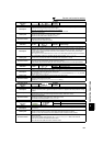
Operation Panel
Indication
RB
FR-PU04
FR-PU07
RB
Name
Regenerative brake prealarm
Description
Appears if the regenerative brake duty reaches or exceeds 85% of the Pr. 70 Special regenerative brake
duty value. When the setting of Pr. 70 Special regenerative brake duty is the initial value (Pr. 70 ="0"), this
warning does not occur. If the regenerative brake duty reaches 100%, a regenerative overvoltage (E.
OV_) occurs.
The RBP signal can be simultaneously output with the [RB] display. For the terminal used for the RBP
signal output, assign the function by setting "7" (positive logic) or "107" (negative logic) in any of Pr. 190
to Pr. 196 (output terminal function selection). (Refer to page 140)
Appears only for the 75K or higher.
Check point
• Check that the brake resistor duty is not high.
• Check that the Pr. 30 Regenerative function selection and Pr. 70 Special regenerative brake duty values are
correct.
Corrective action
• Increase the deceleration time.
•Check the Pr. 30 Regenerative function selection and Pr. 70 Special regenerative brake duty values.
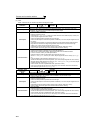
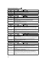
Operation Panel
Indication
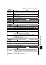
TH
FR-PU04
FR-PU07
TH
Name
Electronic thermal relay function prealarm
Description
Appears if the cumulative value of the Pr. 9 Electronic thermal O/L relay reaches or exceeds 85% of the
preset level. If it reaches 100% of the Pr. 9 Electronic thermal O/L relay setting, a motor overload trip (E.
THM) occurs.
The THP signal can be simultaneously output with the [TH] display. For the terminal used for the THP
signal output, assign the function by setting "8" (positive logic) or "108" (negative logic) in any of Pr. 190
to Pr. 196 (output terminal function selection). (Refer to page 140)
Check point
· Check for large load or sudden acceleration.
·Is the Pr. 9 Electronic thermal O/L relay setting is appropriate? (Refer to page 117.)
Corrective action
· Reduce the load weight or the number of operation times.
· Set an appropriate value in Pr. 9 Electronic thermal O/L relay. (Refer to page 117.)
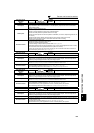
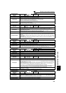
Operation Panel
Indication
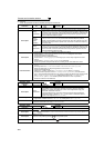
MT
FR-PU04 ————
FR-PU07 MT
Name
Maintenance signal output
Description
Indicates that the cumulative energization time of the inverter has reached a given time.
When the setting of Pr. 504 Maintenance timer alarm output set time is the initial value (Pr. 504 = "9999"),
this protective function does not function.
Check point
The Pr. 503 Maintenance timer setting is larger than the Pr. 504 Maintenance timer alarm output set time
setting. (Refer to page 285.)
Corrective action Setting "0" in Pr. 503 Maintenance timer erases the signal.
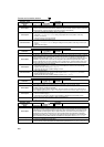
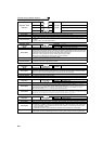
Operation Panel
Indication
CP
FR-PU04 ————
FR-PU07 CP
Name
Parameter copy
Description
Appears when parameters are copied between models with capacities of 55K or lower and 75K or
higher.
Check point
Resetting of Pr.9, Pr.30, Pr.51, Pr.52, Pr.54, Pr.56, Pr.57, Pr.70, Pr.72, Pr.80, Pr.90, Pr.158, Pr.190 to Pr.196,
Pr.557 and Pr.893 is necessary.
Corrective action Set the initial value in Pr. 989 Parameter copy alarm release.
Operation Panel
Indication
FN
FR-PU04
FR-PU07
FN
Name
Fan alarm
Description
For the inverter that contains a cooling fan, appears on the operation panel when the cooling fan
stops due to a fault or different operation from the setting of Pr. 244 Cooling fan operation selection.
Check point Check the cooling fan for an alarm.
Corrective action Check for fan failure. Please contact your sales representative.