


325
Check first when you have a trouble
5
PROTECTIVE FUNCTIONS
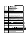
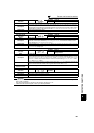
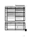
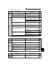
5.5.2 Motor or machine is making abnormal acoustic noise
When operating the inverter with the carrier frequency of 3kHz (6kHz during IPM motor control) or more set in Pr. 72, the
carrier frequency will automatically decrease if the output current of the inverter exceeds the value in parenthesis of the rated
output current on page 346. This may cause the motor noise to increase. But it is not a fault.
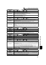
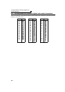
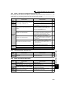
5.5.3 Inverter generates abnormal noise
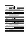
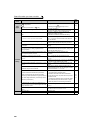
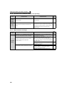
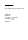
5.5.4 Motor generates heat abnormally
Check
points
Possible Cause Countermeasures
Refer
to
page
Input
signal
Disturbance due to EMI when frequency command is
given from analog input (terminal 1, 2, 4).
Take countermeasures against EMI. 44
Parameter
Setting
Increase the Pr. 74 Input filter time constant if steady
operation cannot be performed due to EMI.
192
Parameter
Setting
No carrier frequency noises (metallic noises) are
generated.
In the initial setting, Pr. 240 Soft-PWM operation selection is
enabled to change motor noise to an unoffending
complex tone. Therefore, no carrier frequency noises
(metallic noises) are generated.
Set Pr. 240 = "0" to disable this function.
182
Resonance occurs. (output frequency)
Set Pr. 31 to Pr. 36 (Frequency jump).
When it is desired to avoid resonance attributable to the
natural frequency of a mechanical system, these
parameters allow resonant frequencies to be jumped.
97
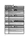
Resonance occurs. (carrier frequency)
Change Pr. 72 PWM frequency selection setting.
Changing the PWM carrier frequency produces an effect
on avoiding the resonance frequency of a mechanical
system or a motor.
182
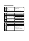
Gain adjustment during PID control is insufficient.
To stabilize the measured value, change the proportional
band (Pr. 129) to a larger value, the integral time (Pr. 130)
to a slightly longer time, and the differential time (Pr. 134)
to a slightly shorter time.
Check the calibration of set point and measured value.
261
Others
Mechanical looseness
Adjust machine/equipment so that there is no
mechanical looseness.
—
Contact the motor manufacturer.
Motor
Operating with output phase loss Check the motor wiring. —
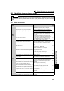
Check
points
Possible Cause Countermeasures
Refer
to
page
Fan
Fan cover was not correctly installed when a cooling fan
was replaced.
Install a fan cover correctly. 336
Check
points
Possible Cause Countermeasures
Refer
to
page
Motor
Motor fan is not working
(Dust is accumulated.)
Clean the motor fan.
Improve the environment.
—
Phase to phase insulation of the motor is insufficient. Check the insulation of the motor. —
Main
Circuit
The inverter output voltage (U, V, W) are unbalanced.
Check the output voltage of the inverter.
Check the insulation of the motor.
333
Parameter
Setting
The Pr. 71 Applied motor setting is wrong. (V/F control,
Simple magnetic flux vector control)
Check the Pr. 71 Applied motor setting. (V/F control,
Simple magnetic flux vector control)
122
—
Motor current is large. Refer to "5.5.11 Motor current is too large" 328