


378
Appendix 4-1 SERIAL number check
Refer to page 2 for the location of the rating plate.
Appendix 4-2 Changed functions
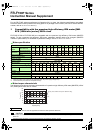
(1) The following functions are available for the 400V class inverters, and the 200V class inverters manufactured in
May 2010 or later. Check the SERIAL on the rating plate of the inverter or on the package.
(2) The following functions are available with the products bearing the SERIAL shown below or later. Check the
SERIAL on the rating plate of the inverter or on the package.
Appendix 4 Specification change
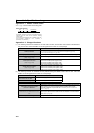
Rating plate example
Symbol Year Month Control number
SERIAL (Serial No.)
The SERIAL consists of one symbol, two characters indicating
production year and month, and six characters indicating
control number.
The last digit of the production year is indicated as the Year,
and the Month is indicated by 1 to 9, X (October), Y
(November), or Z (December.)
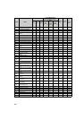
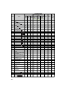
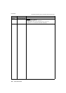
Item Changed functions
Added parameters
Pr. 502 Stop mode selection at communication error (Refer to page 231)
Pr. 779 Operation frequency during communication error (Refer to page 231)
Pr. 997 Fault initiation (Refer to page 289)
Changed parameter setting value Pr. 885 Regeneration avoidance compensation frequency limit value (Refer to page 279)
Added model information monitor
(Refer to page 259)
Modbus-RTU register 44001 to 44013
Added special monitors
(Refer to page 244)
H4D 32-bit cumulative power (lower 16-bit)
H4E 32-bit cumulative power (upper 16-bit)
H4F 32-bit cumulative power (lower 16-bit)
H50 32-bit cumulative power (upper 16-bit)
Added real-time monitors
(Refer to page 256)
40277 32-bit cumulative power (lower 16-bit)
40278 32-bit cumulative power (upper 16-bit)
40279 32-bit cumulative power (lower 16-bit)
40280 32-bit cumulative power (upper 16-bit)
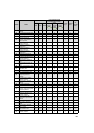
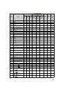
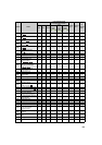
Model SERIAL (Serial No.)
FR-F720P-0.75K to 110K
FR-F740P-0.75K to 160K
08 (August 2010 or later)
FR-F740P-185K or higher
07 (July 2010 or later)
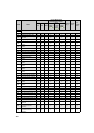
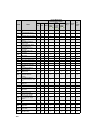
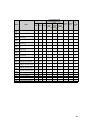
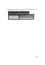
Item Changed functions
Specification change of the IPM
parameter initialization
Pr. 893 Energy saving monitor reference (motor capacity) is initialized for IPM control
when the IPM motor control is selected with the operation panel or IPM
parameter initialization is performed with Pr. 998 IPM parameter initialization.
(Refer to page 81)
LF signal operation while Pr. 502 Stop
mode selection at communication error =
"3."
While Pr. 502 Stop mode selection at communication error = "3," the alarm output
signal (LF) is output from an inverter terminal at a detection of a communication
error. (Refer to page 232)
Added parameter setting value Setting value “4” for Pr. 17 MRS input selection