


362
Heatsink protrusion attachment procedure
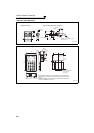
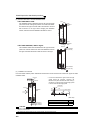
(2) Shift and removal of a rear side installation frame
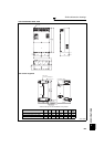
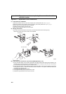
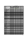
(3) Installation of the inverter
Push the inverter heatsink portion outside the enclosure and fix the enclosure and inverter with upper and lower
installation frame.
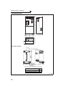
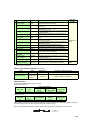
• FR-F740P-250K to 315K
One installation frame is attached to each of the upper and lower
part of the inverter. Change the position of the rear side installa-
tion frame on the upper and lower side of the inverter to the front
side as shown on the right. When changing the installation
frames, make sure that the installation orientation is correct.
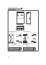
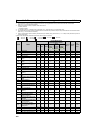
• FR-F740P-185K/220K, 355K or higher
Two installation frames each are attached to the upper and lower
parts of the inverter. Remove the rear side installation frame on
the upper and lower side of the inverter as shown on the right.
CAUTION
· Having a cooling fan, the cooling section which comes out of the enclosure cannot be used in the environment of water
drops, oil, mist, dust, etc.
· Be careful not to drop screws, dust etc. into the inverter and cooling fan section.
Upper
installation
frame
Lower
installation
frame
Shift
Shift
Removal
Upper installation
frame (rear side)
Removal
Lower installation
frame (rear side)
Inverter
Inside the
enclosure
Enclosure
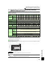
Exhausted air
Installation
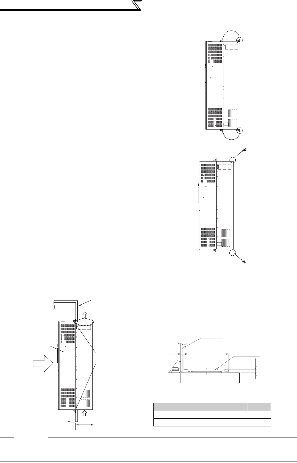
frame
Dimension of
the outside of
the enclosure
Cooling
wind
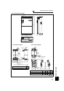
D1
*
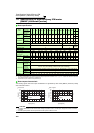
Inverter Model D1(mm)
FR-F740P-185K, 220K 185
FR-F740P-250K to 560K 184
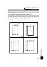
* For the FR-F740P-250K or higher, there are finger
guards behind the enclosure. Therefore, the
thickness of the panel should be less than 10mm(*1)
and also do not place anything around finger guards
to avoid contact with the finger guards.
(Unit: mm)
Enclosure
Finger guard
10*
1
140
6