


226
Communication operation and setting
4.20.2 Wiring and configuration of RS-485 terminals
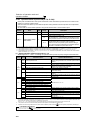
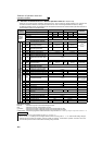
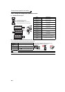
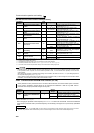
(1) RS-485 terminal layout
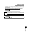
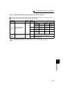
(2) Connection of RS-485 terminals and wires
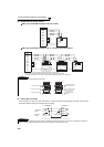
Loosen the terminal screw and insert the cable into the terminal.
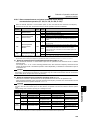
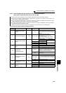
Name Description
RDA1
(RXD1+)
Inverter receive+
RDB1
(RXD1-)
Inverter receive-
RDA2
(RXD2+)
Inverter receive+
(for branch)
RDB2
(RXD2-)
Inverter receive-
(for branch)
SDA1
(TXD1+)
Inverter send+
SDB1
(TXD1-)
Inverter send-
SDA2
(TXD2+)
Inverter send+
(for branch)
SDB2
(TXD2-)
Inverter send-
(for branch)
P5S
(VCC)
5V
Permissible load current 100mA
SG
(GND)
Earth (Ground)
(connected to terminal SD)
Screw size
M2
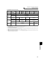
Wire the stripped cable after twisting it to prevent it from
becoming loose. In addition, do not solder it.
Use a blade terminal as necessary.
Tightening
torque
0.22N•m to 0.25N•m
Cable size
0.3mm
2
to 0.75mm
2
Screwdriver
Small flathead screwdriver
(Tip thickness: 0.4mm /tip width: 2.5mm)
CAUTION
Undertightening can cause signal loss or malfunction. Overtightening can cause a short circuit or malfunction due to damage to
the screw or unit.
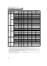
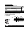
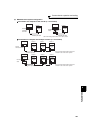
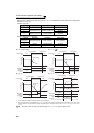
RXD
RDA1
(RXD1+)
RDB1
(RXD1-)
RDA2
(RXD2+)
RDB2
(RXD2-)
SDA1
(TXD1+)
SDB1
(TXD1-)
SDA2
(TXD2+)
SDB2
(TXD2-)
P5S
(VCC)
SG
(GND)
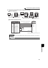
P5S
(VCC)
SG
(GND)
VCC
TXD
OPEN
100Ω
Terminating resistor switch
Factory-set to "OPEN".
Set only the terminating resistor switch of
the remotest inverter to the "100Ω" position.
5mm
Wire stripping length