


348
Common specifications
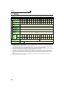
7.2 Common specifications
Control specifications
Control method
High carrier frequency PWM control (V/F control)/Optimum excitation control/Simple magnetic flux vector
control/IPM motor control
Output frequency range
0.5 to 400Hz
Frequency
setting
resolution
Analog input
0.015Hz/60Hz (terminal 2 and 4: 0 to 10V/12-bit)
0.03Hz/60Hz (terminal 2 and 4: 0 to 5V/11bit, 0 to 20mA/approx.11-bit, terminal 1: 0 to ±10V/12-bit)
0.06Hz/60Hz (terminal 1: 0 to ±5V/11-bit)
Digital input
0.01Hz
Frequency
accuracy
Analog input
Within ±0.2% of the maximum output frequency (25°C ±10°C)
Digital input
Within 0.01% of the set output frequency
Speed control range
1:10 under V/F control, 1:15 under Simple magnetic flux vector control, 1:10 under IPM motor control
Voltage/frequency
characteristics
Base frequency can be set from 0 to 400Hz. Constant-torque/variable-torque pattern or adjustable 5 points V/
F can be selected.
Starting
torque
General-purpose
motor control
Under Simple magnetic flux vector control and slip compensation: 120% (at 3Hz)
IPM motor control
50%
Acceleration/deceleration time
setting
0 to 3600s (acceleration and deceleration can be set individually), linear or S-pattern acceleration/
deceleration modes are available.
DC injection brake
General-purpose motor control: Operation frequency (0 to 120Hz), operation time (0 to 10s), operation
voltage (0 to 30%) can be changed.
Stall prevention operation level
Operation current level can be set (0 to 150% variable). Whether to use the function or not can be set.
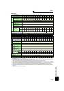
Operation specifications
Frequency
setting signal
Analog input
Terminal 2 and 4: 0 to 10V, 0 to 5V, and 4 to 20mA are available.
Terminal 1: -10 to +10V and -5 to 5V are available.
Digital input
4-digit BCD or 16-bit binary using the setting dial of the operation panel or parameter unit (when used with
the option FR-A7AX)
Start signal
Forward and reverse rotation or start signal automatic self-holding input (3-wire input) can be selected.
Input signals (twelve terminals)
The following signals can be assigned to Pr. 178 to Pr.189 (input terminal function selection): multi-speed
selection, remote setting, second function selection, terminal 4 input selection, JOG operation selection,
automatic restart after instantaneous power failure/flying start, external thermal relay input, inverter run
enable signal (FR-HC/FR-CV connection), FR-HC connection (instantaneous power failure detection), PU
operation external interlock signal, PID control enable terminal, PU-External operation switchover, output
stop, start self-holding selection, forward rotation command, reverse rotation command, inverter reset, PTC
thermistor input, PID forward/reverse action switchover, PU/NET operation switchover, External/NET
operation switchover, command source switchover, DC feeding operation permission, DC feeding cancel,
and PID integral value reset.
Operational functions
Maximum and minimum frequency settings, frequency jump operation, external thermal relay input selection,
polarity reversible operation, automatic restart after instantaneous power failure operation, original operation
continuation at an instantaneous power failure, electronic bypass operation, forward/reverse rotation
prevention, remote setting, second and third function, multi-speed setting, regenerative avoidance, slip
compensation, operation mode selection, PID control, and computer link operation (RS-485)
Output signal
Open collector output (five
terminals)
Relay output (two terminals)
The following signals can be assigned to Pr.190 to Pr.196 (output terminal function selection): inverter running,
up to frequency, instantaneous power failure/undervoltage, overload warning, output frequency detection,
second output frequency detection, regenerative brake prealarm
*1, electronic thermal relay function pre-
alarm, PU operation mode, inverter operation ready, output current detection, zero current detection, PID
lower limit, PID upper limit, PID forward/reverse rotation output, electronic bypass MC1
*2, electronic bypass
MC2
*2, electronic bypass MC3*2, fan fault output, heatsink overheat pre-alarm, inverter running start
command is ON, during deceleration at occurrence of power failure, during PID control activated, PID
deviation limit, IPM motor control
*6, during retry, PID output interruption, pulse train output of output power,
DC feeding, life alarm, fault output 3 (power-off signal), energy saving average value updated timing, current
average value monitor, fault output 2, maintenance timer alarm, remote output, alarm output, and fault output.
Fault code of the inverter can be output (4-bit) from the open collector.
Operating status
When used with
the FR-A7AY, FR-
A7AR (option)
In addition to above, the following signals can be assigned to Pr.313 to Pr.319 (extension output terminal function
selection): control circuit capacitor life, main circuit capacitor life, cooling fan life, and inrush current limit circuit
life. (Only positive logic can be set to the extension terminals of FR-A7AR.)
For meter
Pulse train output
(Max. 2.4kHz: one terminal)
Analog output
(Max. 10VDC: one terminal)
The following signals can be assigned to Pr.54 FM terminal function selection(pulse train output) and Pr. 158 AM
terminal function selection (analog output): output frequency, motor current (steady or peak value), output
voltage, frequency setting value, running speed, converter output voltage (steady or peak value), electronic
thermal relay load factor, input power, output power, load meter, reference voltage output, motor load factor,
energy saving effect, regenerative brake duty
*1, PID set point, and PID measured value.
Indication
Operation
panel
(FR-DU07
)
Parameter
unit
(FR-PU07)
Operating status
Output frequency, motor current (steady or peak value), output voltage, fault display, frequency setting value,
running speed, converter output voltage (steady or peak value), electronic thermal relay load factor, input
power, output power, load meter, cumulative energization time, actual operation time, motor load factor,
cumulative power, energy saving effect, cumulative energy savings, regenerative brake duty
*1, PID set point,
PID measured value, PID deviation, inverter I/O terminal monitor, input terminal option monitor
*3, output
terminal option monitor
*3, option fitting status monitor*4, and terminal assignment status*4.
Fault record
Fault record is displayed when a fault occurs. Past 8 fault records (output voltage/current/frequency/
cumulative energization time right before the fault occurs) are stored.
Interactive
guidance
Function (help) for operation guide and troubleshooting*4