


194
Frequency setting by analog input (terminal 1, 2, 4)
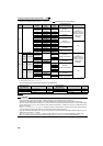
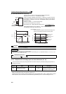
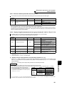
(3) Analog input display unit changing (Pr. 241)
⋅ You can change the analog input display unit (%/V/mA) for analog input bias/gain calibration.
⋅ Depending on the terminal input specification set to Pr. 73 and Pr. 267, the display units of C3 (Pr. 902), C4 (Pr. 903),
C6 (Pr. 904) C7 (Pr. 905) change as shown below.
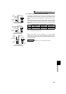
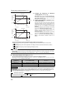
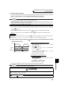
(1) Change the frequency at maximum
analog input (Pr. 125, Pr. 126)
⋅ Set a value in Pr. 125 (Pr. 126) when changing only
the frequency setting (gain) of the maximum analog
input power (current). (C2 (Pr. 902) to C7 (Pr. 905)
setting need not be changed)
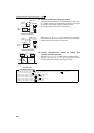
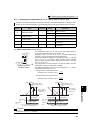
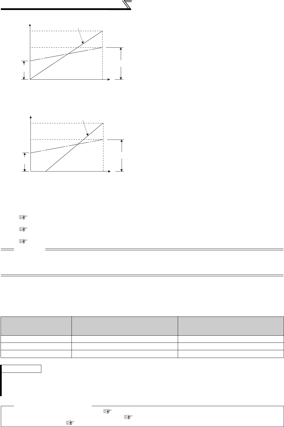
(2) Analog input bias/gain calibration (C2(Pr.
902) to C7(Pr. 905) )
⋅ The "bias" and "gain" functions are used to adjust the
relationship between the input signal entered from
outside the inverter to set the output frequency, e.g. 0
to 5V, 0 to 10V or 0 to 20mADC, and the output
frequency.
⋅ Set the bias frequency of the terminal 2 input using
C2 (Pr. 902). (initial set to the frequency at 0V)
⋅ Using Pr. 125, set the output frequency relative to the
frequency command voltage (current) set in Pr. 73
Analog input selection.
⋅ Set the bias frequency of the terminal 4 input using
C5 (Pr. 904). (initial set to the frequency at 4mA)
⋅ Using Pr. 126, set the output frequency relative to
20mA of the frequency command current (0 to
20mA).
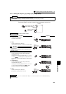
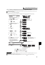
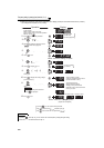
⋅ There are three methods to adjust the frequency setting voltage (current) bias/gain.
(a) Method to adjust any point by application of voltage (current) to across the terminals 2 and 5 (4 and 5).
page 195
(b) Method to adjust any point without application of a voltage (current) to across terminals 2 and 5 (4 and 5).
page 196
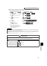
(c) Adjusting only the frequency without adjusting the voltage (current).
page 197
CAUTION
⋅ When the terminal 2 is calibrated to change the inclination of the set frequency, the setting of the terminal 1 is also changed.
⋅ When a voltage is input to the terminal 1 to make calibration, (terminal 2 (4) analog value + terminal 1 analog value) is the analog
calibration value.
⋅ When the voltage/current input specifications were changed using Pr. 73 and Pr. 267, be sure to make calibration.
Analog Command
(terminal 2, 4)
(according to Pr. 73, Pr. 267 )
Pr. 241 = 0 (initial value) Pr. 241 = 1
0 to 5V input 0 to 5V → displayed in 0 to 100%(0.1%). 0 to 100% → displayed in 0 to 5V(0.01V).
0 to 10V input 0 to 10V → displayed in 0 to 100%(0.1%). 0 to 100% → displayed in 0 to 10V(0.01V).
4 to 20mA input 0 to 20mA → displayed in 0 to 100%(0.1%). 0 to 100% → displayed in 0 to 20mA(0.01mA).
REMARKS
⋅ Analog input display is not displayed correctly if voltage is applied to terminal 1 when terminal 1 input specifications (0 to ±5V, 0
to ±10V) and main speed (terminal 2, terminal 4 input) specifications (0 to 5V, 0 to 10V, 0 to 20mA) differ. (For example, 5V
(100%) is analog displayed when 0V and 10V are applied to terminal 2 and terminal 1 respectively in the initial status.
⋅ Set "0" (initial value is 0% display) in Pr. 241 to use.
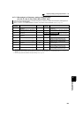
♦ Parameters referred to ♦
Pr. 20 Acceleration/deceleration reference frequency Refer to page 109
Pr. 73 Analog input selection, Pr. 267 Terminal 4 input selection Refer to page 185
Pr. 79 Operation mode selection Refer to page 206
Output frequency
(Hz)
Pr.125
0
0
0
0
C3 (Pr. 902)
Frequency setting signal
Initial value
Bias
Gain
C2
(Pr. 902)
100%
5V
10V
20mA
C4 (Pr. 903)
60Hz
Output frequency
(Hz)
Pr. 126
0
0
0
0
C6 (Pr. 904)
Frequency setting signal
100%
20mA
5V
10V
C7 (Pr. 905)
Initial value
Bias
Gain
20
4
1
2
C5
(Pr. 904)
60Hz