


3
Inverter and peripheral devices
1
OUTLINE
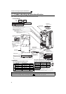
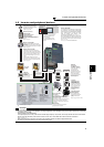
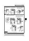
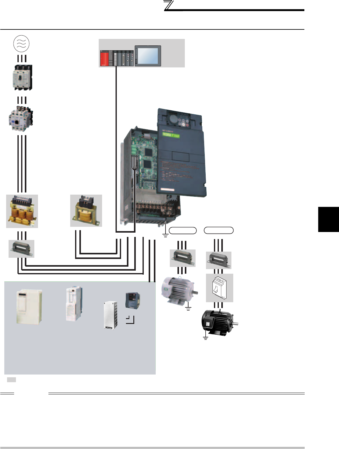
1.2 Inverter and peripheral devices
CAUTION
· Do not install a power factor correction capacitor, surge suppressor or capacitor type filter on the inverter output side. This will
cause the inverter to trip or the capacitor, and surge suppressor to be damaged. If any of the above devices are connected,
immediately remove them.
· Electromagnetic wave interference
The input/output (main circuit) of the inverter includes high frequency components, which may interfere with the communication
devices (such as AM radios) used near the inverter. In this case, set the EMC filter valid to minimize interference.
(Refer to page 15.)
· Refer to the instruction manual of each option and peripheral devices for details of peripheral devices.
· An IPM motor cannot be driven by the commercial power supply.
U VW
: Install these options as required.
Power regeneration
common converter
(FR-CV
*1
)
Power regeneration
converter (MT-RC
*2
)
Resistor unit
(FR-BR
*1
, MT-BR5
*2
)
Brake unit
(FR-BU2, FR-BU
*1
, MT-BU5
*2
)
High power factor
converter
(FR-HC
*1
, MT-HC
*2
)
P/+
P/+
PR
PR
PULL
USB
MODE
RUN
ERR
USER
BAT
BOOT
PULL
POWER
RUN
T.PASS
SD
ERR
MNG
D.LINK
RD
ERR
RUN
T.PASS
SD
ERR
MNG
D.LINK
RD
ERR
Programmable
controller
Three-phase AC power supply
AC reactor
(FR-HAL)
DC reactor
(FR-HEL)
R/L1 S/L2 T/L3
P/+
N/-P/+
P1
UVW
Moulded case circuit
breaker (MCCB)
or earth leakage circuit
breaker (ELB), fuse
Magnetic contactor(MC)
RS-485 terminal block
EMC filter
(ferrite core)
(FR-BSF01, FR-BLF)
Devices connected
to the output
Use within the permissible power supply
specifications of the inverter.
The regeneration braking
capability of the inverter can be
exhibited fully.
Install this as required.
Install the magnetic contactor to ensure safety.
Do not use this magnetic contactor to start and stop
the inverter.
Doing so will cause the inverter life to be shortened.
The inverter can be connected with a
computer such as a programmable
controller and with GOT (human
machine interface).
They support Mitsubishi inverter
protocol and Modbus-RTU (binary)
protocol.
Do not install a power
factor correction capacitor,
surge suppressor or EMC filter (capacitor) on the
output side of the inverter.
When installing a moulded case circuit breaker on
the output side of the inverter, contact each
manufacturer for selection of the moulded case
circuit breaker.
Power supply harmonics
can be greatly suppressed.
Install this as required.
Greater braking capability
is obtained.
Install this as required.
The breaker must be selected carefully since
an in-rush current flows in the inverter at
power on.
Install an EMC filter (ferrite
core) to reduce the
electromagnetic noise
generated from the inverter.
Effective in the range from
about 0.5MHz to 5MHz.
A wire should be wound four
turns at a maximum.
General-
purpose
motor
Human machine interface
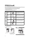
IM connection
IPM connection
Contactor
Example) No-fuse
switch (DSN type)
Install a contactor in an
application where the IPM
motor is driven by the load
even at power-OFF of the
inverter. Do not open or
close the contactor while
the inverter is running
(outputting).
Dedicated IPM motor
(MM-EFS, MM-EF)
Use the specified motor.
IPM motors cannot be driven
by the commercial power
supply.
Earth
(Ground)
Earth
(Ground)
Earth
(Ground)
Earth (Ground)
To prevent an electric shock, always earth
(ground) the motor and inverter.
Reactor (FR-HAL, FR-HEL)
Install reactors to suppress harmonics and to
improve the power factor. An AC reactor (FR-HAL)
(option) is required when installing the inverter near
a large power supply system (1000kVA or more).
The inverter may be damaged if you do not use
reactors.
Select the reactor according to the model.
For the 55K or lower, remove the jumpers across
terminals P/+ and P1 to connect to the DC reactor.
For the 75K or higher, a
DC reactor is supplied.
Always install the reactor.
*1 Compatible with the 55K or lower.
*2 Compatible with the 75K or higher.
EMC filter
(ferrite core)
(FR-BLF)
The 55K or lower has a built-in
common mode choke.
(Refer to page 346)
(Refer to page 4)
(Refer to page 4)
(Refer to page 4.)
Inverter (FR-F700P)
The life of the inverter is influenced by surrounding
air temperature. The surrounding air temperature
should be as low as possible within the permissible
range. Especially when mounting the inverter
inside an enclosure, take cautions of the
surrounding air temperature. (Refer to page 10)
Wrong wiring might lead to damage of the inverter.
The control signal lines must be kept fully away
from the main circuit to protect them from noise.
(Refer to page 14)
Refer to page 15 for the built-in EMC filter.
(Refer to page 359 and 360)
(Refer to page 52.)
(Refer to page 46.)
(Refer to page 38) (Refer to page 40 and 41)
(Refer to page 34)
(Refer to page 42)