83
IPM motor control <IPM>
4
PARAMETERS
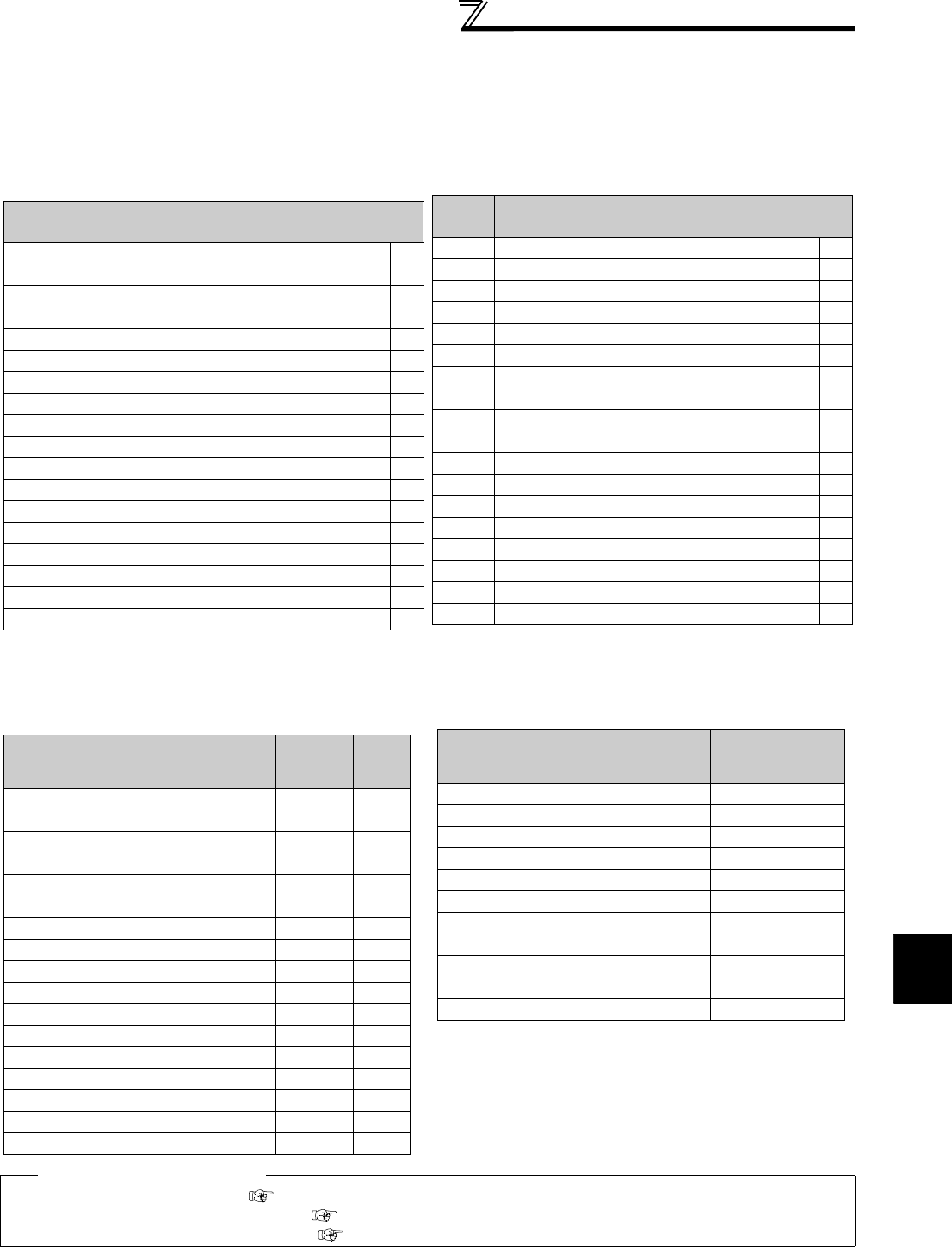
(2) Valid/invalid statuses of I/O terminal functions during the test operation
1)Input terminal function selection (Pr.178 to Pr.189)
All assignable functions are valid.
2)Output terminal function selection (Pr. 190 to Pr. 196)
Some functions have restrictions. For details, refer to the table below.
: Valid, ×: Not output as there is no output current
(3) Valid/invalid statuses of monitor outputs during the test operation
: Valid, ×: Invalid (always displays 0)
U: Displays accumulated value before the test, ⎯: Not monitored
♦ Parameters referred to ♦
Pr.52 DU/PU main display data selection Refer to page 152
Pr.178 to Pr.189 (Input terminal function assignment) Refer to page 133
Pr. 190 to Pr. 196 (Output terminal function selection) Refer to page 140
Signal
name
Function
RUN Inverter running
SU Up to frequency
IPF Instantaneous power failure/undervoltage
OL Overload alarm ×
FU Output frequency detection
FU2 Second output frequency detection
RBP Regenerative brake pre-alarm
THP Electronic thermal O/L relay pre-alarm ×
PU PU operation mode
RY Inverter operation ready
Y12 Output current detection
Y13 Zero current detection
FDN PID lower limit
FUP PID upper limit
RL PID forward/reverse rotation output
FAN Fan fault output
FIN Heatsink overheat pre-alarm
RUN3 Inverter running and start command is on
Y46 During deceleration at occurrence of power failure
PID During PID control activated
Y48 PID deviation limit
IPM IPM motor control
Y64 During retry
SLEEP PID output interruption
Y79 Pulse train output of output power ×
Y85 DC feeding
Y90 Life alarm
Y91 Fault output 3 (power-off signal)
Y92 Energy saving average value updated timing
Y93 Current average value monitor signal
ALM2 Fault output 2
Y95 Maintenance timer signal
REM Remote output
LF Alarm output
ALM Fault output
9999 No function ⎯
Signal
name
Function
*1 Monitor output is valid or invalid depending on the monitor type
(operation panel display, parameter unit display, or terminal FM/
AM). For details, refer to page 152.
*2 When the operation is switched to the test operation, "0" is
displayed. When IPM motor control is selected again after a test
operation, the output current peak value and the electronic thermal
relay load factor from the last operation are displayed.
Monitoring items
DU/PU
monitor
display
AM/FM
output
Output frequency
Output current ××
Output voltage ××
Fault display ⎯
Frequency setting value
Running speed
Converter output voltage
Regenerative brake duty
Electronic thermal relay load factor ×
*2 × *2
Output current peak value × *2 × *2
Converter output voltage peak value
Input power ××
Output power ××
Load meter ××
Cumulative energization time ⎯
Reference voltage output ⎯
Actual operation time ⎯
Motor load factor ××
Cumulative power U ⎯
Energy saving effect ××
Cumulative saving energy U ⎯
PID set point
PID measured value
PID deviation ⎯
Input terminal status ⎯
Output terminal status ⎯
Option input terminal status ⎯
Option output terminal status ⎯
Monitoring items
DU/PU
monitor
display
AM/FM
output


