


327
Check first when you have a trouble
5
PROTECTIVE FUNCTIONS
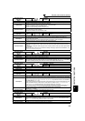
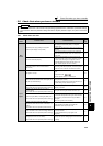
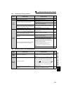
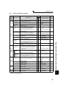
5.5.8 Speed varies during operation
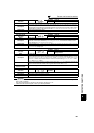
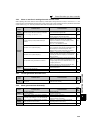
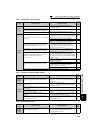
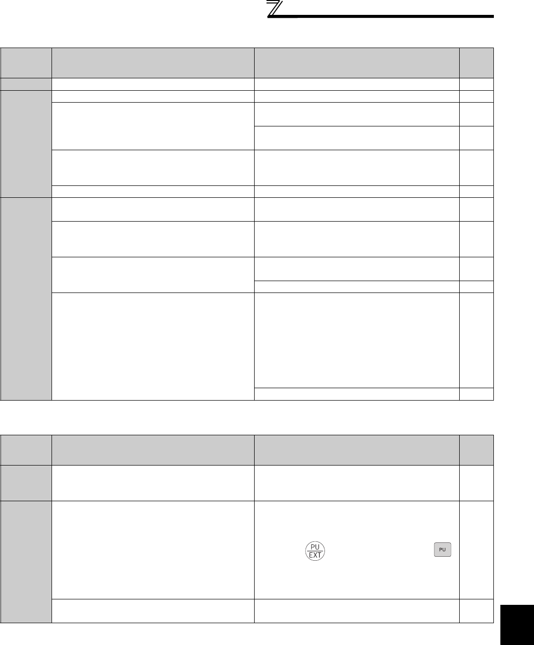
5.5.9 Operation mode is not changed properly
Check
points
Possible Cause Countermeasures
Refer
to
page
Load
Load varies during an operation. (V/F control) Select Simple magnetic flux vector control 89
Input
signal
Frequency setting signal is varying. Check the frequency setting signal. —
The frequency setting signal is affected by EMI.
Set filter to the analog input terminal using Pr. 74 Input
filter time constant.
192
Take countermeasures against EMI, such as using
shielded wires for input signal lines.
46
Malfunction is occurring due to the undesirable current
generated when the transistor output unit is connected.
Use terminal PC (terminal SD when source logic) as a
common terminal to prevent a malfunction caused by
undesirable current.
30
Multi-speed command signal is chattering. Take countermeasures to suppress chattering. —
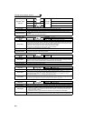
Parameter
Setting
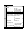
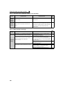
Fluctuation of power supply voltage is too large.
Change the Pr. 19 Base frequency voltage setting (about
3%) under V/F control.
98
The Pr.80 Motor capacity setting is inappropriate for the
inverter and motor capacities under Simple magnetic
flux vector control and IPM motor control.
Check the Pr. 80 Motor capacity setting. 89
Wiring length is too long for V/F control, and a voltage
drop occurs.
Adjust Pr. 0 Torque boost by increasing with 0.5%
increments for low-speed operation.
87
Change to Simple magnetic flux vector control. 89
Hunting occurs by the generated vibration, for example,
when structural rigidity at load side is insufficient.
Disable automatic control functions, such as energy
saving operation, fast-response current limit function,
regeneration avoidance function, Simple magnetic flux
vector control and stall prevention.
For PID control, set smaller values to Pr.129 PID
proportional band and Pr.130 PID integral time.
Lower the control gain, and adjust to increase the
stability.
—
Change Pr. 72 PWM frequency selection setting.
182
Check
points
Possible Cause Countermeasures
Refer
to
page
Input
signal
Start signal (STF or STR) is ON.
Check that the STF and STR signals are OFF.
When either is ON, the operation mode cannot be
changed.
206
Parameter
Setting
Pr. 79 setting is improper.
When Pr. 79 Operation mode selection setting is "0" (initial
value), the inverter is placed in the External operation
mode at input power ON. To switch to the PU operation
mode, press on the operation panel (press
when the parameter unit (FR-PU04/FR-PU07) is used) .
At other settings (1 to 4, 6, 7), the operation mode is
limited accordingly.
206
Operation mode and a writing device do not
correspond.
Check Pr. 79, Pr. 338, Pr. 339, Pr. 550, Pr. 551, and select
an operation mode suitable for the purpose.
206,
219