


154
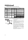
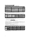
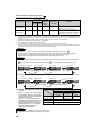
Monitor display and monitor output signal
*1 Frequency setting to output terminal status on the PU main monitor are selected by "other monitor selection" of the parameter unit (FR-PU04
, FR-PU07
).
*2 The cumulative energization time and actual operation time are accumulated from 0 to 65535 hours, then cleared, and accumulated again from 0.
When the operation panel (FR-DU07) is used, the time is displayed up to 65.53 (65530h) in the indication of 1h = 0.001, and thereafter, it is added
up from 0.
*3 The actual operation time is not added up if the cumulative operation time before power supply-OFF is less than 1h.
*4 When using the parameter unit (FR-PU04/FR-PU07), "kW" is displayed.
*5 The setting depends on capacities. (55K or lower/75K or higher)
*6 Since the panel display of the operation panel is 4 digits in length, the monitor value of more than "9999" is displayed as "----".
*7 When the output current is less than the specified current level (5% of the rated inverter current), the output current is monitored as 0A. Therefore,
the monitored value of an output current and output power may be displayed as "0" when using a much smaller-capacity motor compared to the
inverter or in other instances that cause the output current to fall below the specified value.
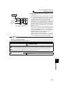
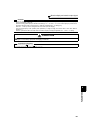
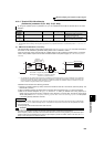
Option input
terminal status
⎯
56
×× ⎯
Displays ON/OFF status of the input terminal
of the digital input option (FR-A7AX) on the
DU
(refer to page 155 for details)
Option output
terminal status
⎯
57
×× ⎯
Displays ON/OFF status of the output
terminal of the digital output option (FR-
A7AY) and relay output option (FR-A7AR)
on the DU (refer to page 155 for details)
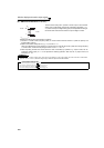
REMARKS
⋅ By setting "0" in Pr. 52, the monitoring of output speed to fault display can be selected in sequence by .
⋅ When the operation panel (FR-DU07) is used, the displayed units are Hz, V and A only and the others are not displayed.
⋅ The monitor set in Pr. 52 is displayed in the third monitor position. (The output voltage monitor is changed.)
Note that load meter and motor load factor are displayed in the second monitor (output current).
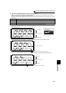
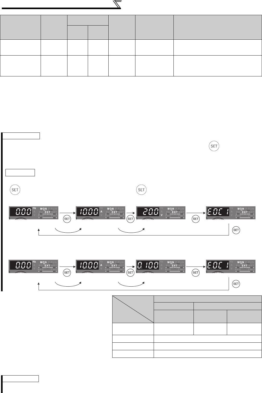
* The monitor displayed at powering ON is the first monitor. Display the monitor you want to display on the first monitor and hold down
for 1s. (To return to the output frequency monitor, hold down for 1s after displaying the output frequency monitor.)
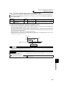
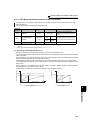
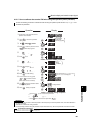
Example)When Pr. 52 is set to "20" (cumulative energization time), the monitor is displayed on the operation panel as described
below.
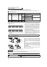
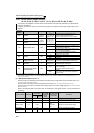
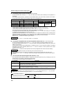
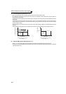
(2) Display set frequency during stop
(Pr. 52)
⋅ When Pr. 52 is set to "100", the set frequency
monitor is displayed during a stop and the
output frequency monitor is displayed during
operation. (LED of Hz flickers during stop
and is lit during running.)
⋅ When Pr.52 = "100", the set frequency
displayed at a stop indicates frequency to be
output when the start command is ON.
Different from the frequency setting based
on displayed when Pr.52 = "5", the value
maximum/minimum frequency and
frequency jump is displayed.
Pr. 52
0 100
During
running/stop
During stop
During
running
Output frequency
Output
frequency
Set
frequency
Output
frequency
Output current Output current
Output voltage Output voltage
Fault display Fault display
REMARKS
⋅ During an error, the output frequency at error occurrence appears.
⋅ During MRS, the values displayed are the same as during a stop.
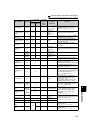
Types of Monitor Increments
Pr. 52 Parameter
Setting Value
Pr. 54 (FM)
Pr. 158 (AM)
Parameter
Setting
Value
Full-scale value
of the terminal
FM and AM
Description
DU LED
PU main
monitor
Initial value
• Power-on monitor (first monitor) • Second monitor • Third monitor • Fault monitor
With fault
Output current monitor
Output voltage monitor
Output frequency monitor
• Power-on monitor (first monitor) • Second monitor • Third monitor • Fault monitor
With fault
Output current monitor
Output frequency monitor
Cumulative energization time monitor