


265
Special operation and frequency control
4
PARAMETERS
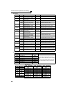
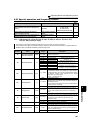
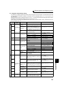
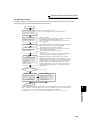
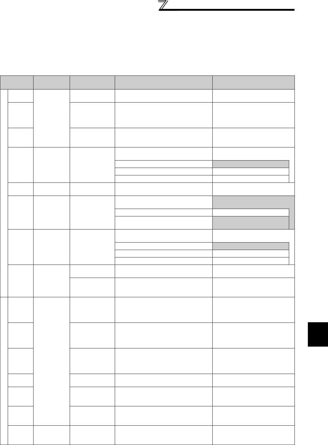
(4) I/O signals and parameter setting
⋅ Turn ON the X14 signal to perform PID control. When this signal is OFF, PID action is not performed and normal
inverter operation is performed. (However, turning X14 ON is not necessary when Pr.128 = "50, 51, 60, 61, 110,
111, 120, 121".)
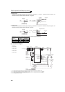
⋅ Enter the set point across inverter terminals 2-5 or into Pr. 133 and enter the measured value signal across inverter
terminals 4 and 5. At this time, set any of "20, 21, 120, 121" in Pr. 128.
⋅ When entering the externally calculated deviation signal, enter it across terminals 1 and 5. At this time, set any of
"10, 11, 110, 111" in Pr. 128.
Signal
Terminal
Used
Function Description Parameter Setting
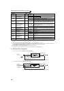
Input
X14
Depending on
Pr. 178 to Pr.
189
PID control
selection
Turn ON X14 to perform PID control. Set 14 in any of Pr. 178 to Pr. 189.
X64
PID forward/
reverse action
switchover
By turning ON X64, forward action can be
selected for PID reverse action (
Pr. 128
=
10, 20, 110, 120), and reverse action for
forward action (
Pr. 128
= 11, 21, 111, 121).
Set 64 in any of Pr. 178 to Pr. 189.
X72
PID integral value
reset
ON: Integral and differential values are
reset
OFF: Normal processing
Set 72 in any of Pr. 178 to Pr. 189.
22
*4 Set point input
Enter the set point for PID control.
Pr. 128 = 20, 21, 120, 121
Pr. 133 =9999
0 to 5V................0 to 100%
Pr. 73 = 1 *1, 3, 5, 11, 13, 15
0 to 10V..............0 to 100%
Pr. 73 = 0, 2, 4, 10, 12, 14
0 to 20mA...........0 to 100%
Pr. 73 = 6, 7, 16, 17
PU ⎯ Set point input
Set the set value (Pr. 133) from the
operation panel or parameter unit.
Pr. 128 = 20, 21, 120, 121
Pr. 133 = 0 to 100%
11
Deviation signal
input
Input the deviation signal calculated
externally.
Pr. 128 = 10 *1, 11, 110, 111
-5V to +5V..........-100% to +100%
Pr. 73 = 2, 3, 5, 7, 12, 13, 15, 17
-10V to +10V......-100% to +100%
Pr. 73 = 0, 1 *1, 4, 6, 10, 11, 14,
16
44
*4
Measured value
input
Input the signal from the detector
(measured value signal).
Pr. 128 = 20, 21, 120, 121
4 to 20mA...........0 to 100%
Pr. 267 = 0 *1
1 to 5V................0 to 100%
Pr. 267 = 1
2 to 10V..............0 to 100%
Pr. 267 = 2
Communi-
cation
*2
⎯
Deviation value
input
Input the deviation value from L
ON
W
ORKS
,
CC-Link communication.
Pr. 128 = 50, 51
Set value,
measured value
input
Input the set value and measured value
from L
ONWORKS , CC-Link
communication.
Pr. 128 = 60, 61
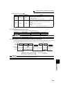
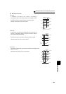
Output
FUP
Depending on
Pr. 190 to Pr.
196
Upper limit output
Output to indicate that the measured
value signal exceeded the upper limit
value (Pr. 131).
Pr. 128 =20, 21, 60, 61, 120, 121
Pr. 131 ≠ 9999
Set 15 or 115 in any of Pr. 190 to Pr.
196.
*3
FDN Lower limit output
Output when the measured value signal
falls below the lower limit (Pr. 132).
Pr. 128 =20, 21, 60, 61, 120, 121
Pr. 132 ≠ 9999
Set 14 or 114 in any of Pr. 190 to Pr.
196.
*3
RL
Forward (reverse)
rotation direction
output
"Hi" is output to indicate that the output
indication of the parameter unit is forward
rotation (FWD), and "Low" to indicate that
it is reverse rotation (REV) or stop (STOP).
Set 16 or 116 in any of Pr. 190 to Pr.
196.
*3
PID
During PID
control activated
Turns ON during PID control.
Set 47 or 147 in any of Pr. 190 to Pr.
196.
*3
SLEEP
PID output
interruption
Turns ON when the PID output
interruption function is performed.
Pr. 575 ≠ 9999
Set 70 or 170 in any of Pr. 190 to Pr.
196.
*3
Y48 PID deviation limit
Output when the absolute value of
deviation exceeds the limit value.
Pr. 553 ≠ 9999
Set 48 or 148 in any of Pr. 190 to Pr.
196.
*3
SE SE
Output terminal
common
Common terminal for terminals assigned
to FUP signal, FDN signal, RL signal, PID
signal, SLEEP signal, and Y48 signal