


142
Function assignment of external
terminal and control
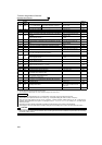
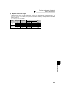
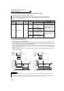
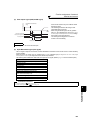
(2) Inverter operation ready signal (RY signal) and inverter running signal (RUN, RUN3 signal)
*1 This signal turns OFF during power failure or undervoltage.
*2 Output is shutoff in conditions like a fault and when the MRS signal is ON.
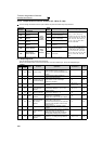
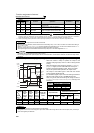
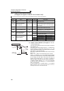
96 196 REM Remote output
Output to the terminal when a value is set to
the parameter.
Pr. 495 to Pr. 497
148
98 198 LF Alarm output
Output when an alarm (fan failure or
communication error warning) occurs.
Pr. 121, Pr. 244
229,
281
99 199 ALM Fault output
Output when the fault occurs. The signal
output is stopped when the fault is reset.
⎯ 143
9999 ⎯ No function ⎯⎯⎯
*1 Note that when the frequency setting is varied using an analog signal or of the operation panel (FR-DU07), the output of the SU (up to
frequency) signal may alternate ON and OFF depending on that varying speed and the timing of the varying speed due to acceleration/
deceleration time setting. (The output will not alternate ON and OFF when the acceleration/deceleration time setting is "0s".)
*2 When a power supply reset is performed, the fault output 2 signal (ALM2) turns OFF as soon as the power supply switches OFF.
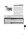
REMARKS
⋅ The same function may be set to more than one terminal.
⋅ When the function is executed, the terminal conducts at the setting of any of "0" to "99", and does not conduct at the setting of
any of "100" to "199".
⋅ When Pr. 76 Fault code output selection = "1", the output signals of the terminals SU, IPF, OL and FU are switched as set in Pr. 76.
(When an inverter fault occurs, the signal output is switched to the fault code output.)
⋅ The output assignment of the terminal RUN and fault output relay are as set above regardless of Pr. 76.
CAUTION
⋅ Changing the terminal assignment using Pr. 190 to Pr. 196 (output terminal function selection) may affect the other functions. Set
parameters after confirming the function of each terminal.
⋅ Do not assign signals which repeat frequent ON/OFF to terminal ABC1, terminal ABC2. Otherwise, the life of the relay contact
decreases.
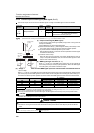
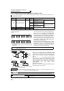
⋅ When the inverter is ready to operate, the output of the
operation ready signal (RY) is ON. It is also on during inverter
running.
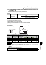
⋅ When the inverter's output frequency reaches Pr. 13 Starting
frequency or higher (0.01Hz under IPM motor control), the
inverter running signal (RUN) is output. During an inverter
stop or DC injection brake operation, the output is OFF.
⋅ The output of the RUN3 signal is ON when the inverter
running and start signals are ON.
(For the RUN3 signal, output is ON if the starting command is
ON even when a fault occurs or the MRS signal is ON.
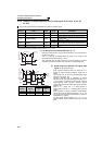
⋅
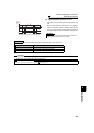
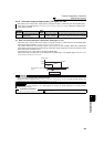
When using the RY, RUN and RUN3 signals, assign functions to
Pr. 190 to Pr. 196 (output terminal selection function) referring to the
table below.
Inverter
Status
Output
Signal
Start
Signal is
OFF
(during
stop)
Start
Signal is
ON
(during
stop)
Start
Signal is
ON
(during
running)
Under DC
Injection
Brake
Output Shutoff
*2
Automatic Restart after
Instantaneous Power Failure
Coasting
Restarting
Start Signal
is ON
Start Signal
is OFF
Start Signal
is ON
Start Signal
is OFF
RY ON ON ON ON OFF ON *1 ON
RUN OFF OFF
ON OFF OFF OFF ON
RUN3 OFF ON ON ON ON OFF ON OFF ON
REMARKS
⋅ RUN signal is assigned to the terminal RUN in the initial setting.
⋅ During IPM motor control, the RUN signal is output about 100ms after turning ON the start command (STF, STR). The delay is
due to the magnetic pole detection.
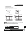
Setting
Signal
Name
Function Operation
Related
Parameters
Refer
to Page
Positive
Logic
Negative
Logic
RUN
Power
supply
Output frequency
STF
RH
RY
RUN3
Pr. 13
Starting
frequency
DC injection brake
operation point
DC injection
brake
operation
Reset
processing
Time
ON
ON
ON
ON
ON
ON
OFF
OFF
OFF
OFF
OFF
Output
Signal
Pr. 190 to Pr. 196 Setting
Positive logic Negative logic
RY
11 111
RUN 0100
RUN3
45 145