


259
Communication operation and setting
4
PARAMETERS
Model information monitor
............... Specifications differ according to the date assembled. Refer to page 378 to check the SERIAL number.
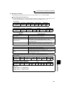
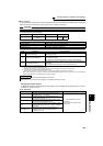
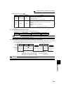
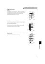
(7) Pr. 343 Communication error count
You can check the cumulative number of communication errors.
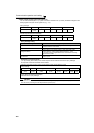
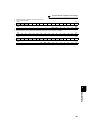
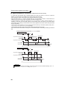
(8) Output signal LF "alarm output (communication error warnings)"
During a communication error, the alarm signal (LF signal) is output by open collector output. The LF signal
can be assigned to the output terminal using any of Pr. 190 to Pr. 196 (output terminal function selection).
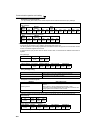
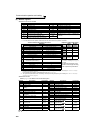
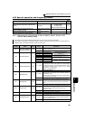
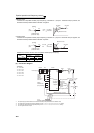
Register Definition Read/Write Remarks
44001 to
44010
Inverter type Read
Reading inverter type in ASCII code.
"H20" (blank code) is set for blank area
Example of FR-F720P
H46, H52, H2D, H46, H37, H32, H30, H50, H20 .........................H20
44011 to
44013
Capacity Read
Reading inverter capacity in ASCII code.
Data is read in increments of 0.1kW, and rounds down to 0.01kW
increments
"H20" (blank code) is set for blank area
Example
0.75K............... " 7" (H20, H20, H20, H20, H20, H37)
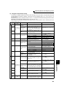
Parameters Setting Range Minimum Setting Range Initial Value
343 (Read only) 1 0
CAUTION
The number of communication errors is temporarily stored into the RAM. As it is not stored into the EEPROM, performing
a power supply reset or inverter reset clears the value to 0.
CAUTION
The LF signal can be assigned to the output terminal using any of Pr.190 to Pr.196. Changing the terminal assignment may affect
the other functions. Set parameters after confirming the function of each terminal.
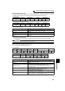
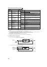
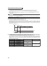
Alarm data
Reply data
Master
Slave
0
Signal LF
Normal dataAlarm data Alarm data
12
OFF
ON
OFF OFF
ON
Not increased
Turns OFF when normal data is received
Alarm data :
Normal data
Reply data
Communication error count is increased in
synchronization with leading edge of LF signal
Data resulting in
communication error.
Communication
Error count
(Pr.343)