


103
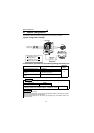
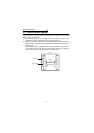
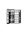
Function Block Diagram
4
PLC FUNCTION
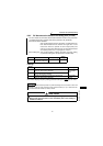
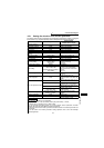
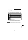
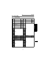
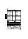
4.3.1 Setting list of built-in PLC function parameter
The built-in PLC function parameters are designed to specify the ranges of using the
PLC function, e.g. program capacity, device assignment and various functions.
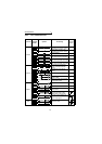
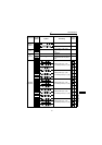
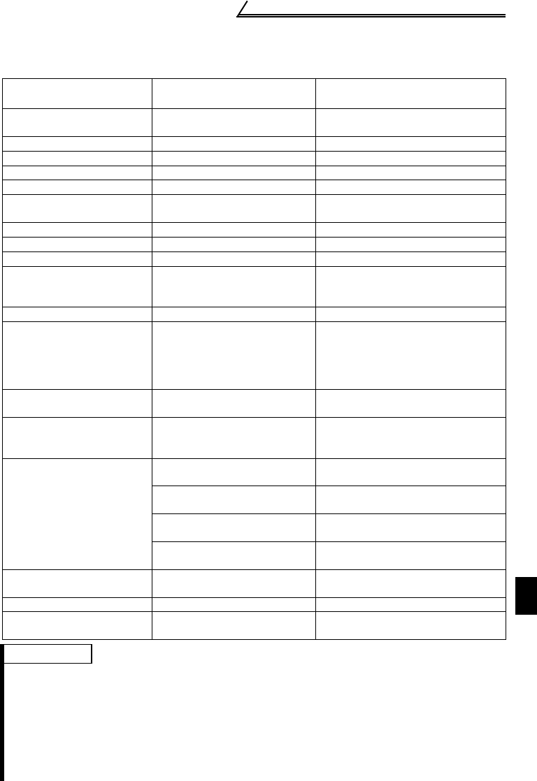
Item GX Developer Default
Setting Range
<Usable device range>
Sequence program
capacity
6k steps 1k step
File register capacity None Cannot be set (default)
Comment capacity None Cannot be set (default)
Status latch None Cannot be set (default)
Sampling trace None Cannot be set (default)
Microcomputer program
capacity
None Cannot be set (default)
Latch range setting L1000 to 2047 Cannot be set (invalid if set)
Link range setting None Cannot be set (default)
I/O assignment None Cannot be set (default)
Internal relay, latch relay,
step relay setting
M0 to 999
L1000 to 2047
None for S
L and S cannot be set.
(Operates as M if set)
<M0 to 63>
Watchdog timer setting 200ms 10 to 2000ms
Timer setting
100ms: T0 to 199
10ms: T200 to 255
(100ms timers since only T0 to 7
are available)
8 points (set in units of 16 points)
for 100ms, 10ms and retentive
timers. Timers have consecutive
numbers.
<T0 to T7>
Counter setting Without interrupt counters
Cannot be set (default)
<C0 to C7>
Remote run/pause None
Can be set using X0 to 1F.
Otherwise invalid. Pause does not
function.
Error-time operation mode
Fuse blow: Continued
Setting invalid (since there are no
fuses)
I/O verify error: Stop
Setting invalid
(since there are no I/O modules)
Operation error: Continued
Setting invalid (since there are no
operation check errors)
Special function module
check error: Stop
Setting invalid (since there are no
special modules)
STOP → RUN output mode
Operation status prior to
STOP is re-output.
Prior to STOP/after operation
execution
Print title registration None Cannot be set
Keyword registration None
Online setting cannot be made but
parameter setting is valid.
REMARKS
•The following functions are not supported.
1. Constant scan, 2. Latch (device data backup for power failure), 3. Pause,
4. Status latch, 5. Sampling trace, 6. Offline switch
For the operation processing outline, I/O control method, device explanation and other
details, refer to the FR-C500 Series Programming Manual.
•If parameter clear of the inverter is performed, the above built-in PLC function parameters are
not cleared.
• For the built-in PLC function parameter setting operation, refer to the GX Developer
Operating Manual.