


33
Connection of Stand-Alone Option Units
1
INSTALLATION AND WIRING
1.11 Connection of Stand-Alone Option Units
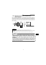
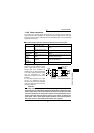
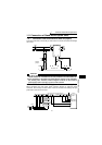
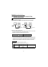
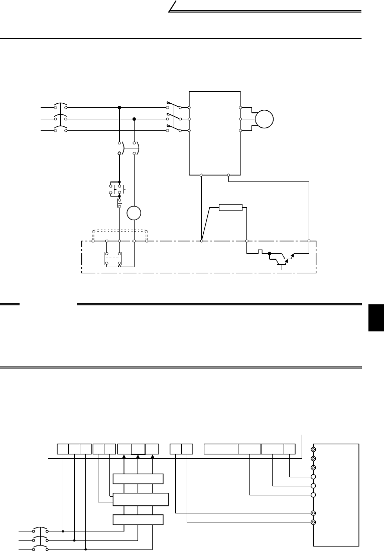
1.11.1 Connection of the conventional BU brake unit (option)
Connect the BU brake unit correctly as shown below. Incorrect connection will damage
the inverter.
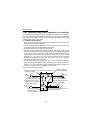
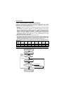
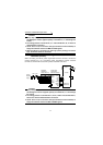
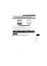
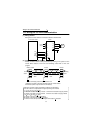
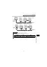
1.11.2 Connection of the FR-HC high power factor converter (option)
When connecting the high power factor converter (FR-HC) to suppress power
harmonics, wire securely as shown below. Incorrect connection will damage the high
power factor converter and inverter.
CAUTION
1. The wiring distance between the inverter, brake unit and discharge resistor
should be within 2m. If twisted wires are used, the distance should be within 5m.
2. If the transistors in the brake unit should fail, the resistor can be extremely
hot, causing a fire. Therefore, install a magnetic contactor on the inverter's
power supply side to shut off a current in case of failure.
MC
U
V
W
IM
HC
HBHA TB
P
OCR
PR
NFB
PC
ON
OFF
MC
OCR
N
MC
R
S
T
N
P
Inverter
Motor
Remove
jumpers.
Discharge resistor
BU brake unit
NFB
RST R4S4T4
NP
Y1orY2 RDY RSO SE
MRS (Note 3)
RES (Note 3)
SD
FR-HCL01
R4 S4 T4
R3
S3 T3
R2
S2
T2
R
S
T
MC2
MC1
MC1MC2
T
S (Note 1)
R
P
N
Power
supply
From FR-HCL02
External box
High power factor converter (FR-HC)
Inverter