


84
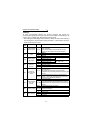
Computer Link Operation Setting
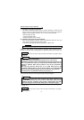
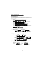
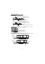
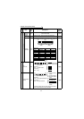
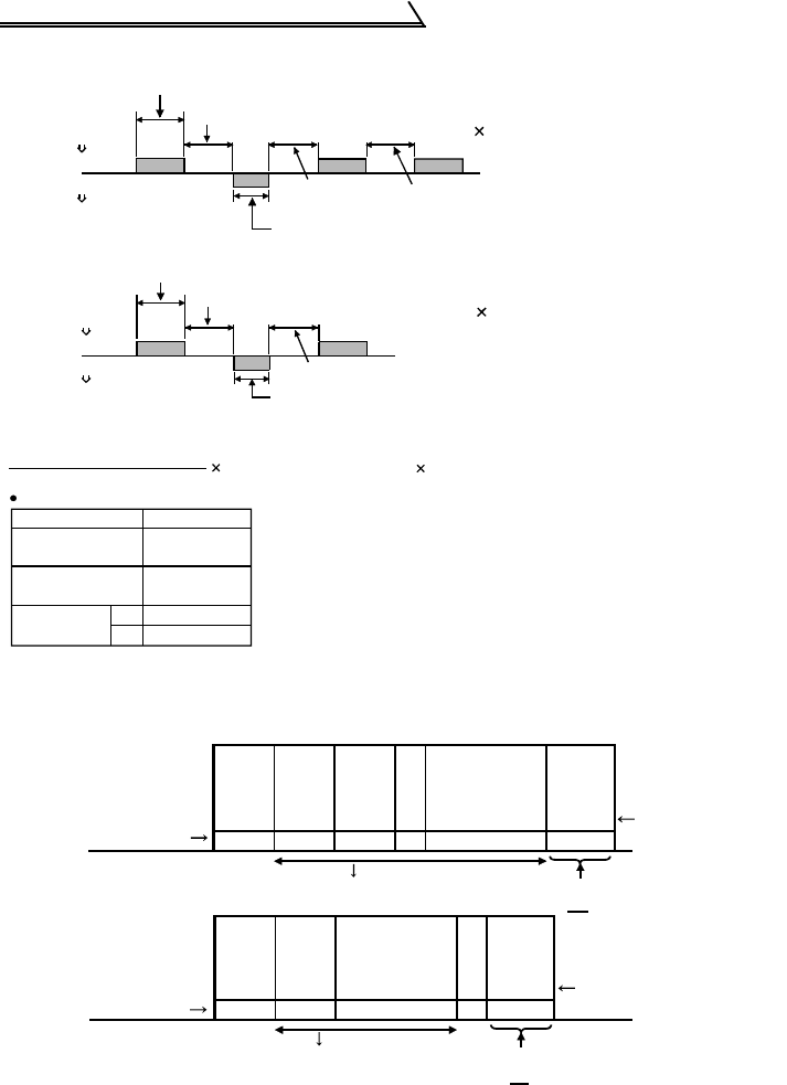
6) Response time
7) Sum chck code
The sum check code is 2-digit ASCII (hexadecimal) representing the lower 1 byte (8
bits) of the sum (binary) derived from the checked ASCII data.
(12ms)
STX
ACK
ENQ
ENQ
(12ms)
Data sending time (Refer to the following calculation expression)
omputer
Inverter
Inverter
omputer
Inverter data processing time = waiting time + data check time
(setting 10ms)
10ms or more
required
10ms or more required
Data sending time
(Refer to the following calculation expression)
Data sending time (Refer to the following calculation expression)
Computer
Inverter
Inverter
Computer
Inverter data processing time = waiting time + data check time
(setting 10ms)
10ms or more required
Data sending time (Refer to the following calculation expression)
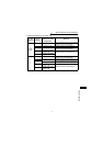
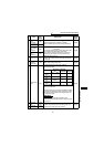
1
(bps)
0
=
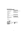
[Data sending time calculation expression]
Communication speed
Number of data characters
Communication specification
(Total number of bits)
(See below)
Data sending time (s)
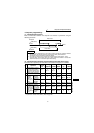
Communication specifications
Name
Number of Bits
Stop bit length
1 bit
2 bits
Data length
Parity check
Yes
No
7 bits
8 bits
1 bit
In addition to the bits in the left table,
1 bit is required for the start bit.
Minimum total number of bits ... 9 bits
Maximum total number of bits ... 12 bits
(Refer to page 82)
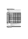
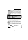
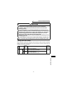
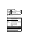
(Example 1)
E
N
Q
10 1E1 07AD F4
H05 H30 H31 H31H45 H31 H30 H37 H41 H44 H46 H34
H H H H H H H H H
30+31+45+31+31+30+37+41+44 = 1F4
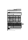
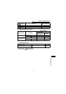
S
T
X
0 117 0
30
H02 H30 H31 H37H31 H37 H30 H03
H33 H30
H H H H H H
30+31+31+37+37+30
E
T
X
7
Computer to inverter
ASCII code
Station
number
Instruction
code
Waiting
time
Data
Sum
check
code
Binary code
H
Example 2)
Inverter to computer
ASCII code
Station
number
Read data
Sum
check
code
Binary code
130
Sum
=
H
Sum