


49
Chapter 7
Chapter 6
Chapter 5
Chapter 4
Chapter 3
Chapter 2
Chapter 1
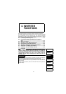
3. INVERTER
FUNCTIONS
This chapter explains the inverter functions (inverter parameters).
For simple variable-speed operation of the inverter, the factory settings
of the parameters may be used as they are. Set the necessary
parameters to meet the load and operational specifications. Always
read the instructions before using the functions.
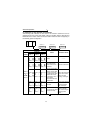
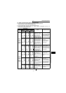
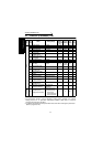
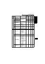
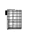
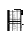
3.1 Function (Parameter) List.................................... 50
3.2 List of Parameters Classified by Purpose of
Use.........................................................................
55
3.3 Basic Functions.................................................... 56
3.4 Operation Panel Display Selection ..................... 67
3.5 I/O Terminal Function Selection.......................... 68
3.6 Operation Selection Function Parameters......... 70
3.7 Computer Link Operation Setting....................... 79
3.8 Parameter Unit (FR-PU04) Setting ...................... 93
CAUTION
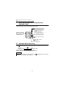
As the contact input terminals RL, RM, RH, STF, STR and open
collector output terminals RUN, SQ, ALM can be changed in
functions by parameter setting, their signal names used for the
corresponding functions are used in this chapter (with the
exception of the wiring examples). Note that they are not
terminal names.
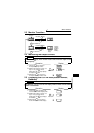
REMARKS
Using the parameter unit (FR-PU04), parameter copy allows the parameter
values to be copied to another inverter (only the FR-C500 series).
After batch-reading the parameters of the copy source inverter, you can
connect the parameter unit to the copy destination inverter and batch-write
the parameters.
For the operation procedure, refer to the instruction manual of the parameter
unit (FR-PU04).