36
Wiring for CC-Link Communication
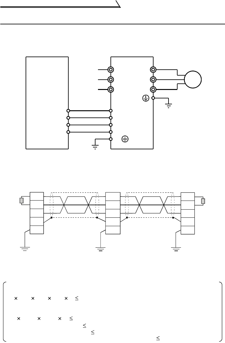
1.13 Wiring for CC-Link Communication
(1) Wiring method
Wiring of the inverter and CC-Link master module is shown below.
(2) Connection of multiple inverters
Multiple inverters can be Factory-Automated by sharing a link system as one
remote device station of CC-Link and monitoring control with a PLC user
program.
1)Maximum number of inverters connected to one master station
42 inverters (when only inverters are connected)
U
V
W
R
S
T
DA
DB
DG
SLD
FG
DA
DB
DG
SLD
C-Link master module
Power
supply
Inverter
Motor
DA
DB
DG
SLD
FG
DA
DB
DG
SLD
FG
DA
DB
DG
SLD
FG
Master module
erminating
esistor*
Shielded twisted
cable
Shielded twisted
cable
Inverter Inverter
Terminating
resistor*
*Use the terminating resistors supplied with the PLC.
When there are other modules, the following conditions must be satisfied
since the number of occupied stations changes depending on the modules.
A: Number of remote I/O stations 64 stations
B: Number of remote device stations 42 stations
C: Number of local, standby master and intelligent device stations 26 stations
{(1 a)+(2 b)+(3 c)+(4 d)} 64
a: Number of one-station occupying modules
b: Number of two-station occupying modules
c: Number of three-station occupying modules
d: Number of four-station occupying modules
{(16 A)+(54 B)+(88 C)} 2304


