


117
Inverter Status Monitoring, Special Registers for
Control
4
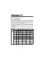
PLC FUNCTION
4.7
Inverter Status Monitoring, Special Registers for Control
You can assign the data for grasping and changing the inverter's operation status to
D9133 - D9147 and read/write them from the user sequence. (Refer to page 112 for
the list.)
4.7.1 Data that can be read at all times
The following data can always be read. They are automatically refreshed every time
the END instruction is executed.
(1) Operation monitor
The following data devices are always read-enabled (write-disabled) to allow you to
monitor the output frequency, output current and output voltage of the inverter. Note
the setting units.
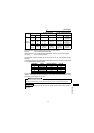
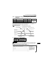
(2) Error history (error codes and error definitions)
The inverter stores the error codes of the errors that occurred.
The error codes of up to four errors are stored in the order as shown below and are
always read-enabled (write-disabled).
<Error code storing method details>
Refer to page 155 for alarm definition details.
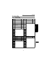
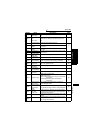
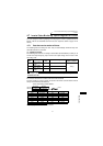
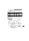
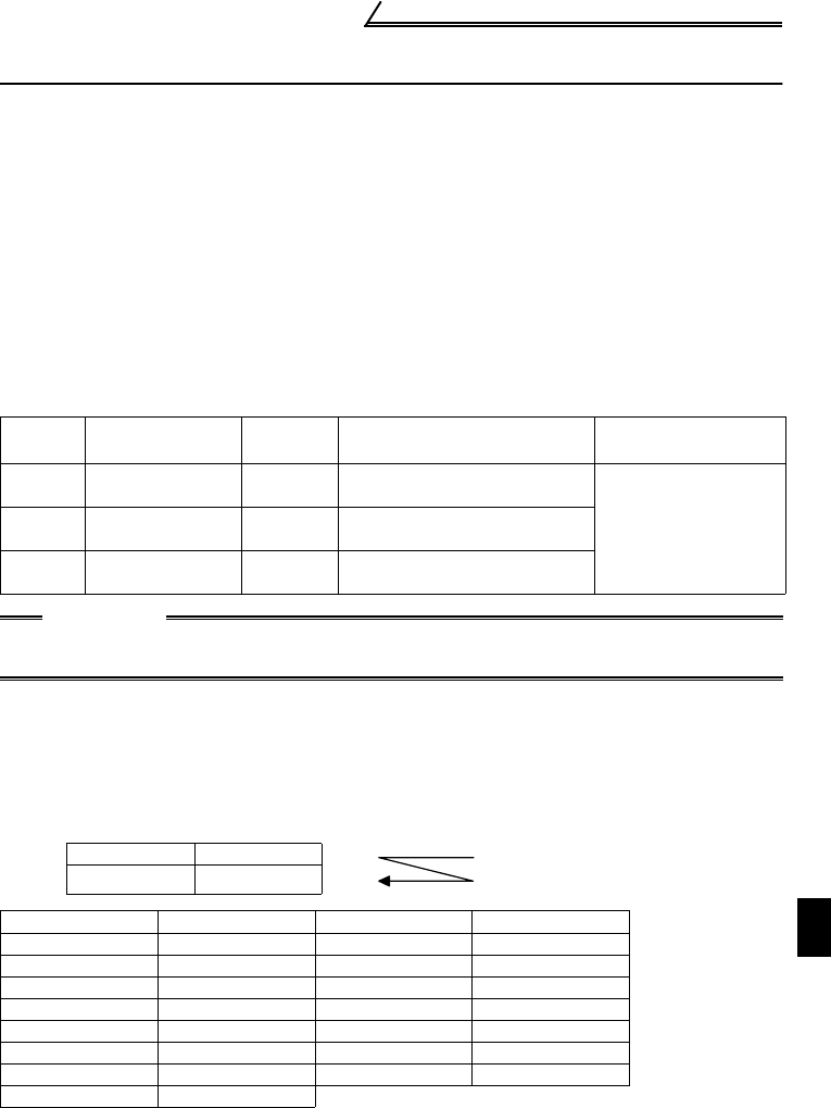
Device
No.
Name
Setting
Unit
Data Example
Data Access
Enable Condition
D9133
Output frequency
monitor
0.01Hz Device data 6000 → 60.00Hz
AlwaysD9134
Output current
monitor
0.01A Device data 200 → 2.00A
D9135
Output voltage
monitor
0.1V Device data 1000 → 100.0V
CAUTION
The frequency can be set in increments of 0.01Hz but actual operation is performed in
increments of 0.1Hz.
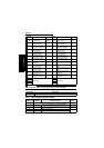
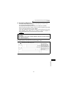
b15 to b8 b7 to b0
D9136 Error history 2 Error history 1
D9137 Error history 4 Error history 3
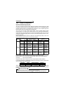
Error Code Error Definition Error Code Error Definition
H00 No alarm H31 E.THM
H10 E.OC1 H40 E.FIN
H11 E.OC2 H60 E.OLT
H12 E.OC3 H80 E.GF
H20 E.OV1 H90 E.OHT
H21 E.OV2 HB0 E.PE
H22 E.OV3 HB1 E.PUE
H30 E.THT
Older
Newer