


190
Instructions for compliance with U.S. and Canadian
Electrical Codes
5. Wiring of the power supply and motor
For wiring the input (R, S, T) and output (U, V, W) terminals of the inverter, use the
UL-listed copper wires (rated at 75
°
C) and round crimping terminals. Crimp the
crimping terminals with the crimping tool recommended by the terminal maker.
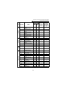
6. Motor overload protection
These inverters provide solid state motor overload protection.
Set parameter 9 using the following instructions,
(Pr. 9 "electronic thermal O/L relay").
<Setting>
•Set the rated current [A] of the motor.
(Normally set the rated current at 50Hz.)
•Setting "0" makes the electronic overcurrent protection (motor protective function)
invalid. (The inverter's protective function is valid).
•When using a Mitsubishi constant-torque motor, first set "1" in Pr. 71 to choose the
100% continuous torque characteristic in the low-speed range. Then, set the rated
motor current in Pr. 9.
CAUTION
•
When two or more motors are connected to the inverter, they cannot be protected by
the electronic overcurrent protection. Install an external thermal relay to each motor.
•
When the difference between the inverter and motor capacities is large and the setting
is small, the protective characteristics of the electronic overcurrent protection will be
deteriorated.
In this cause, use an external thermal relay.
•
A special motor cannot be protected by the electronic overcurrent protection. Use an
external thermal relay.
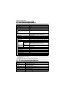
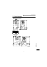
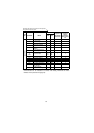
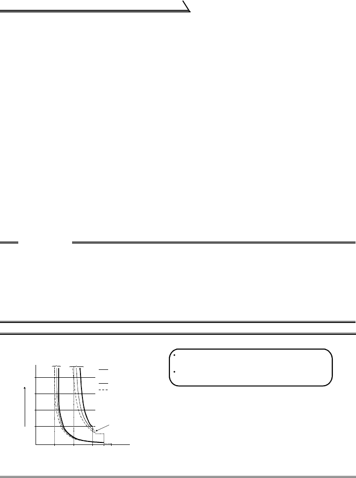
Reference: Motor overload protection characteristics
0 50 100 150 180200
240
180
120
60
Operation time (s)
50% setting
(Note 1, 2)
100% setting
(Note 2)
(Note 1) When you set the 50% value (current
value) of the rated inverter output current.
(Note 2) The % value denotes the percentage of
the current value to the rated inverter
output current, not to the rated motor current.
(Note 3) This characteristic curve will be described
even under operation of 6Hz or higher
when you set the electronic overcurrent
protection dedicated to the Mitsubishi
constant-torque motor.
30Hz or higher
(Note 3)
Inverter output current (%)
(% to rated inverter output current)
Electronic overcurrent
protection for transistor
protection
20Hz
10Hz
Protection activating range
Range on the right of characteristic curve
Normal operating range
Range on the left of characteristic curve