


9
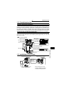
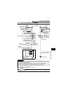
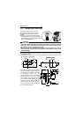
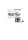
Control Circuit
1
INSTALLATION AND WIRING
*1. Do not connect terminals SD and PC each other or to the ground.
For sink logic (factory setting), terminal SD acts as the common terminal of contact input.
For source logic, terminal PC acts as the common terminal of contact input. (Refer to
page 12 for the way to switch between them.)
*2. Low indicates that the open collector output transistor is on (conducts). High indicates
that the transistor is off (does not conduct).
*3. RL, RM, RH, MRS, OH, RES, STF, STR, SQ signal, without function selection (Refer to
page 68 for input terminal function selection.)
*4. RUN, OL, ALM signal, without function selection (Refer to page 69 for output terminal
function selection.)
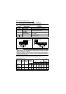
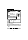
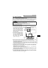
Communication
—
RS-485
connector
• Compliant standard: EIA Standard RS-485
• Transmission form: Multidrop link system
• Communication speed: Maximum 19200bps
• Overall distance: 500m
—
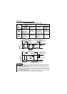
Symbol
Terminal
Name
Description
Rating
Specifications