


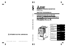

I
CONTENTS
1. INSTALLATION AND WIRING 1
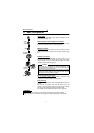
1.1 Basic Configuration.....................................................................2
1.2 Precautions for Use ....................................................................3
1.3 Installation of the Inverter............................................................3
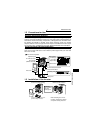
1.4 Terminal Connection Diagram ....................................................5
1.5 Wiring of the Power Supply and Motor........................................6
1.5.1 Description of the main circuit terminals ....................................................... 6
1.5.2 Layout and wiring of the main circuit terminals............................................. 6
1.5.3 Cables, wiring lengths, crimping terminals, etc............................................. 6
1.6 Earthing (Grounding) Precautions...............................................7
1.7 Control Circuit .............................................................................8
1.7.1 Description of the control circuit terminals .................................................... 8
1.7.2 Layout and wiring of the control circuit terminals........................................ 10
1.7.3 Layout and wiring of the CC-Link terminals ................................................ 11
1.7.4 Changing the control logic .......................................................................... 12
1.7.5 RS-485 Connector ...................................................................................... 14
1.7.6 Connection of the parameter unit (FR-PU04) ............................................. 14
1.8 Input Terminals .........................................................................15
1.8.1 Run (start) and stop (STF, STR)................................................................. 15
1.8.2 External frequency selection (RH, RM, RL) ................................................ 17
1.8.3 Control circuit common terminals (SD, SE) ................................................ 18
1.8.4 Signal inputs by contactless switches......................................................... 18
1.9 How to Use the Input Signals (Assigned Terminals RL, RM, RH,
STR, SQ) ..................................................................................19
1.9.1 Multi-speed setting (RL, RM, RH signals): Pr. 60 to Pr. 63, Pr. 65, Pr. 505
setting "0, 1, 2"............................................................................................ 19
1.9.2 Output shut-off (MRS signal): Pr. 60 to Pr. 63, Pr. 65, Pr. 505 setting "6".. 19
1.9.3 External thermal relay input: Pr. 60 to Pr. 63, Pr. 65, Pr. 505 setting "7".... 19
1.9.4 Reset signal: Pr. 60 to Pr. 63, Pr. 65, Pr. 505 setting "10".......................... 20
1.9.5 Start (forward rotation) signal: Pr. 65 setting "17"....................................... 20
1.9.6 Sequence start: Pr. 60 to Pr. 63, Pr. 65, Pr. 505 setting "50" ..................... 21
1.9.7 No function: Pr. 60 to Pr. 63, Pr. 65, Pr. 505 setting "9998" ....................... 21
1.9.8 Start (reverse rotation) signal: Pr. 63 setting "9999"................................... 21
1.10 Peripheral Devices....................................................................22
1.10.1 Peripheral device list................................................................................... 22
1.10.2 Leakage current and installation of earth (ground) leakage circuit breaker 22
1.10.3 Power-off and magnetic contactor (MC) ..................................................... 26
1.10.4 Regarding the installation of the power factor improving reactor................ 27
1.10.5 Regarding noises and the installation of the noise filter.............................. 28
1.10.6 Power harmonics ........................................................................................ 29