


10
Control Circuit
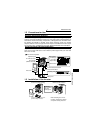
1.7.2 Layout and wiring of the control circuit terminals
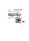
*Information on bar terminals
Introduced products (as of April, '02): Phoenix Contact Co., Ltd.
Bar terminal crimping tool: CRIMPFOX ZA3 (Phoenix Contact Co., Ltd.)
1)Terminals SD and SE are common terminals of the I/O signals. Do not earth
(ground) these common terminals.
2) Use shielded or twisted cables for connection to the control circuit terminals and run
them away from the main and power circuits (including the 200V relay sequence circuit).
3)The input signals to the control circuit are micro currents. When contacts are
required, use two or more parallel micro signal contacts or a twin contact to prevent
a contact fault.
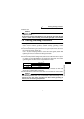
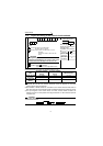
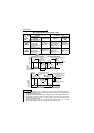
Control circuit terminal block
Loosen the terminal screw and insert the cable into the
terminal.
Screw size: M3 (SD, PC, SE terminals),
M2 (other than on the left)
Tightening torque: 0.5N•m to 0.6N•m (SD, PC, SE
terminals)
0.22N•m to 0.25N•m (other than the
above)
Cable size: 0.3mm
2
to 0.75mm
2
Screwdriver: Small screwdriver
(Tip thickness: 0.4mm/tip width: 2.5mm)
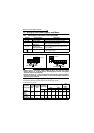
Terminal Screw
Size
Bar Terminal Model
(With insulating
sleeve)
Bar Terminal Model
(Without insulating
sleeve)
Wire Size (mm
2
)
M3 (SD, PC, SE
terminals)
Al 0.5-6WH A 0.5-6 0.3 to 0.5
Al 0.75-6GY A 0.75-6 0.5 to 0.75
M2 (other than
above)
Al 0.5-6WH A 0.5-6 0.3 to 0.5
CAUTION
When using the bar terminal (without insulating sleeve), use care so that the twisted
wires do not come out.
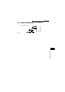
SD PC
STR RL RM RH SQ RUNALMSTF
SE
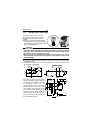
CAUTION
Undertightening can cause cable disconnection or
malfunction. Overtightening can cause a short circuit
or malfunction due to damage to the screw or unit.
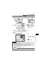
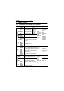
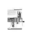
6
(mm)
5
Cable stripping size
Wire the stripped cable after
twisting it to prevent it from
becoming loose.
In addition, do not solder it. *
SD, PC, SE
terminals
Other than
the above