


106
PLC Instructions
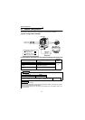
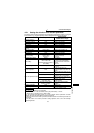
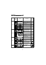
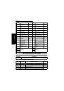
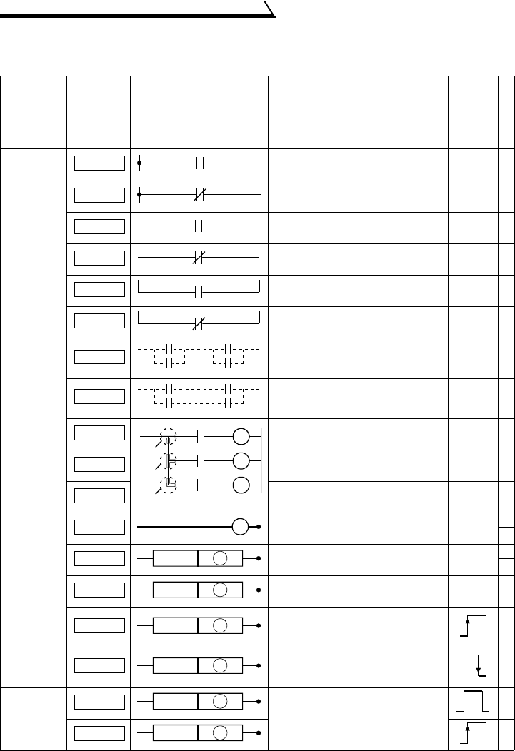
4.4.2 PLC instruction list
Classification
Instruction
Symbol
Symbol Processing
Execution
Condition
Number of Steps
Contacts
Logical operation start
(Operation start at N/O contact)
1
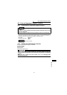
Logical NOT operation start
(Operation start at N/C contact)
1
Logical product
(N/O contact series connection)
1
Logical product NOT
(N/C contact series connection)
1
Logical sum
(N/O contact parallel connection)
1
Logical sum NOT
(N/C contact parallel connection)
1
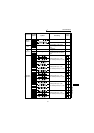
Connection
AND between logical blocks
(series connection between
blocks)
1
OR between logical blocks
(parallel connection between
blocks)
1
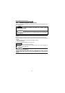
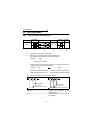
Stores the operation result. 1
Reads the operation result
stored in MPS.
1
Reads and resets the operation
result stored in MPS.
1
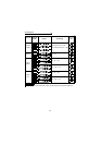
Outputs
Outputs device.
1
3
Sets device.
1
3
Resets device.
1
3
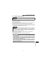
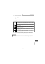
Produces a pulse lasting one
program scan time on the
leading edge of input signal.
3
Produces a pulse lasting one
program scan time on the trailing
edge of input signal.
3
Shift 1-bit device shift
3
3
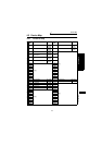
L D
LDI
AND
ANI
O R
ORI
ANB
ORB
MPS
MPS
MRD
MPP
MRD
MPP
OUT
SET
SET D
RST
RST
D
PLS
PLS D
PLF
PLF
D
SFT
SFT
D
SFTP
SFTP
D