


34
Connection of Stand-Alone Option Units
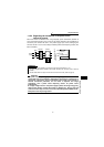
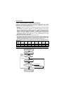
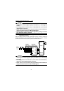
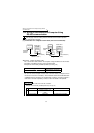
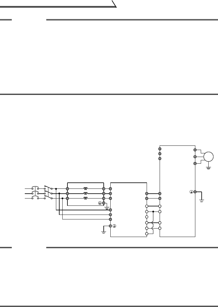
1.11.3 Connection of the power regeneration common
converter (FR-CV)
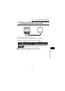
When connecting the FR-CV power regeneration common converter, connect the
inverter terminals (P/+, N/-) and FR-CV power regeneration common converter
terminals as shown below so that their symbols match with each other.
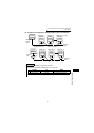
CAUTION
1. Always keep the power input terminals R, S and T open. Incorrect connection
will damage the inverter. Opposite polarity of terminals N/-, P/+ will damage the
inverter.
2. The voltage phases of terminals R, S, T and terminals R4, S4, T4 must be
matched before connection.
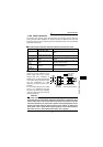
3. Use Pr. 60 to Pr. 63, Pr. 65 and Pr. 505 (input terminal function selection) to
assign the terminals used for the MRS and RES signals.
4. When the FR-HC is connected, use sink logic (factory setting). For source
logic, the FR-HC cannot be connected.
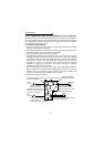
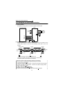
CAUTION
1. Always keep R/L1, S/L2 and T/L3 of the inverter open. Incorrect connection
will damage the inverter. Opposite polarity of terminals N/-, P/+ will damage
the inverter.
2. The voltage phases of terminals R/L11, S/L21, T/MC1 and terminals R2/L1,
S2/L2, T2/L3 must be matched before connection.
3. Use Pr. 60 to Pr. 63, Pr. 65 and Pr. 505 (input terminal function selection) to
assign the terminals used for the RES and MRS signals.
MC1
NFB
R/L11
S/L21
T/L31
R2/L12
S2/L22
T2/L32
R2/L1
S2/L2
T2/L3
R/L11
S/L21
T/MC1
P/L+
U
V
W
IM
PC
SD
MRS(Note 3)
RES(Note 3)
P24
SD
RDYB
RSO
SE
RDYA
N/L-
R
S
T
P
N
3
-phase
A
C power
s
upply
Dedicated
stand-alone
reactor (FR-CVL)
FR-CV power
regeneration
common converter
(Note 1)
Inverter